

458
M. N. Bojnordi and P. Behnam
Analog Bit
Counter
Memristive Cell
Memory
DRAM
DRAM
DRAM
DRAM
Banks
CPU
RRAM
RRAM
RRAM
RRAM
MISC
Array
1
Array
m
...
...
...
DDRx Interfaces
Reduction Tree
Chip
Controller
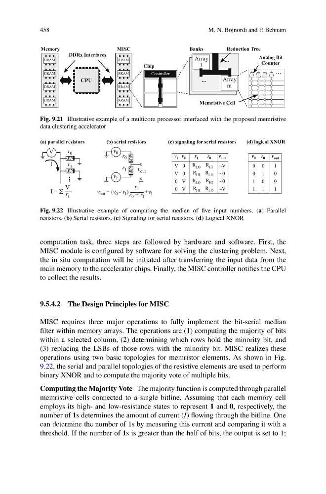
Fig. 9.21 Illustrative example of a multicore processor interfaced with the proposed memristive
data clustering accelerator
v 1
V
V
0
0
v 0
0
0
V
V
r 1
R LO
R HI
R LO
R HI
r 0
R HI
R LO
R HI
R LO
v out
~V
~0
~0
~V
(c) signaling for serial resistors
v 0
0
0
1
1
r 0
0
1
0
1
v out
1
0
0
1
(d) logical XNOR
(b) serial resistors
v 0
v 1
v out
r 1
r 0
+v 1
v out = (v 0 - v 1 ) r 0 + r 1
r 1
(a) parallel resistors
V
r 0
...
r 1
I
I = r i
V
Fig. 9.22 Illustrative example of computing the median of five input numbers. (a) Parallel
resistors. (b) Serial resistors. (c) Signaling for serial resistors. (d) Logical XNOR
computation task, three steps are followed by hardware and software. First, the
MISC module is configured by software for solving the clustering problem. Next,
the in situ computation will be initiated after transferring the input data from the
main memory to the accelerator chips. Finally, the MISC controller notifies the CPU
to collect the results.
9.5.4.2 The Design Principles for MISC
MISC requires three major operations to fully implement the bit-serial median
filter within memory arrays. The operations are (1) computing the majority of bits
within a selected column, (2) determining which rows hold the minority bit, and
(3) replacing the LSBs of those rows with the minority bit. MISC realizes these
operations using two basic topologies for memristor elements. As shown in Fig.
9.22, the serial and parallel topologies of the resistive elements are used to perform
binary XNOR and to compute the majority vote of multiple bits.
Computing the Majority Vote The majority function is computed through parallel
memristive cells connected to a single bitline. Assuming that each memory cell
employs its high- and low-resistance states to represent 1 and 0, respectively, the
number of 1s determines the amount of current (I) flowing through the bitline. One
can determine the number of 1s by measuring this current and comparing it with a
threshold. If the number of 1s is greater than the half of bits, the output is set to 1;
M. N. Bojnordi and P. Behnam
Analog Bit
Counter
Memristive Cell
Memory
DRAM
DRAM
DRAM
DRAM
Banks
CPU
RRAM
RRAM
RRAM
RRAM
MISC
Array
1
Array
m
...
...
...
DDRx Interfaces
Reduction Tree
Chip
Controller
Fig. 9.21 Illustrative example of a multicore processor interfaced with the proposed memristive
data clustering accelerator
v 1
V
V
0
0
v 0
0
0
V
V
r 1
R LO
R HI
R LO
R HI
r 0
R HI
R LO
R HI
R LO
v out
~V
~0
~0
~V
(c) signaling for serial resistors
v 0
0
0
1
1
r 0
0
1
0
1
v out
1
0
0
1
(d) logical XNOR
(b) serial resistors
v 0
v 1
v out
r 1
r 0
+v 1
v out = (v 0 - v 1 ) r 0 + r 1
r 1
(a) parallel resistors
V
r 0
...
r 1
I
I = r i
V
Fig. 9.22 Illustrative example of computing the median of five input numbers. (a) Parallel
resistors. (b) Serial resistors. (c) Signaling for serial resistors. (d) Logical XNOR
computation task, three steps are followed by hardware and software. First, the
MISC module is configured by software for solving the clustering problem. Next,
the in situ computation will be initiated after transferring the input data from the
main memory to the accelerator chips. Finally, the MISC controller notifies the CPU
to collect the results.
9.5.4.2 The Design Principles for MISC
MISC requires three major operations to fully implement the bit-serial median
filter within memory arrays. The operations are (1) computing the majority of bits
within a selected column, (2) determining which rows hold the minority bit, and
(3) replacing the LSBs of those rows with the minority bit. MISC realizes these
operations using two basic topologies for memristor elements. As shown in Fig.
9.22, the serial and parallel topologies of the resistive elements are used to perform
binary XNOR and to compute the majority vote of multiple bits.
Computing the Majority Vote The majority function is computed through parallel
memristive cells connected to a single bitline. Assuming that each memory cell
employs its high- and low-resistance states to represent 1 and 0, respectively, the
number of 1s determines the amount of current (I) flowing through the bitline. One
can determine the number of 1s by measuring this current and comparing it with a
threshold. If the number of 1s is greater than the half of bits, the output is set to 1;