

9 Emerging Hardware Technologies for IoT Data Processing
449
that the input data for a selected layer are streamed into the accelerator. The chip
controller distributes the data stream among relevant banks internally. Local buffers
are used to collect the convolutional results at the MB-CNN banks. At the end of
every computation, the accelerator notified the software to read the results from the
MB-CNN chip and to proceed with the subsequent layers operations.
9.4.4.2 Bank Organization
Each MB-CNN bank consists of a bank controller, a reduction network with
an H-tree topology, and a set of data arrays. The bank controller is responsible
for managing computed partial bit-counts within a local on-die buffer. Moreover,
the controller is in charge of configuring the full adders and comparators of the
reduction tree for computing the final sum. During each MB-CNN convolution,
partial bit-counts are computed using the memory arrays. The counts are then
merged into a single bit-count while being transferred through the reduction tree
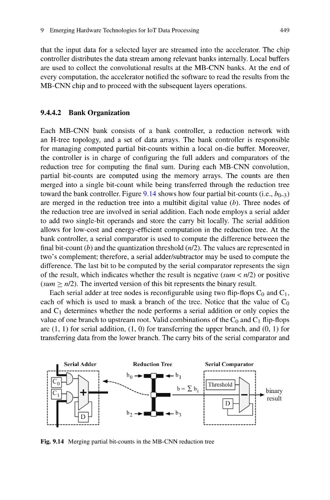
toward the bank controller. Figure 9.14 shows how four partial bit-counts (i.e., b 0–3 )
are merged in the reduction tree into a multibit digital value (b). Three nodes of
the reduction tree are involved in serial addition. Each node employs a serial adder
to add two single-bit operands and store the carry bit locally. The serial addition
allows for low-cost and energy-efficient computation in the reduction tree. At the
bank controller, a serial comparator is used to compute the difference between the
final bit-count (b) and the quantization threshold (n/2). The values are represented in
two’s complement; therefore, a serial adder/subtractor may be used to compute the
difference. The last bit to be computed by the serial comparator represents the sign
of the result, which indicates whether the result is negative (sum < n/2) or positive
(sum ≥ n/2). The inverted version of this bit represents the binary result.
Each serial adder at tree nodes is reconfigurable using two flip-flops C 0 and C 1 ,
each of which is used to mask a branch of the tree. Notice that the value of C 0
and C 1 determines whether the node performs a serial addition or only copies the
value of one branch to upstream root. Valid combinations of the C 0 and C 1 flip-flops
are (1, 1) for serial addition, (1, 0) for transferring the upper branch, and (0, 1) for
transferring data from the lower branch. The carry bits of the serial comparator and
b 1
b 3
b 0
b 2
b = b i
Serial Adder
D
C 1
C 0
Reduction Tree
D
Threshold
binary
result
Serial Comparator
Fig. 9.14 Merging partial bit-counts in the MB-CNN reduction tree
449
that the input data for a selected layer are streamed into the accelerator. The chip
controller distributes the data stream among relevant banks internally. Local buffers
are used to collect the convolutional results at the MB-CNN banks. At the end of
every computation, the accelerator notified the software to read the results from the
MB-CNN chip and to proceed with the subsequent layers operations.
9.4.4.2 Bank Organization
Each MB-CNN bank consists of a bank controller, a reduction network with
an H-tree topology, and a set of data arrays. The bank controller is responsible
for managing computed partial bit-counts within a local on-die buffer. Moreover,
the controller is in charge of configuring the full adders and comparators of the
reduction tree for computing the final sum. During each MB-CNN convolution,
partial bit-counts are computed using the memory arrays. The counts are then
merged into a single bit-count while being transferred through the reduction tree
toward the bank controller. Figure 9.14 shows how four partial bit-counts (i.e., b 0–3 )
are merged in the reduction tree into a multibit digital value (b). Three nodes of
the reduction tree are involved in serial addition. Each node employs a serial adder
to add two single-bit operands and store the carry bit locally. The serial addition
allows for low-cost and energy-efficient computation in the reduction tree. At the
bank controller, a serial comparator is used to compute the difference between the
final bit-count (b) and the quantization threshold (n/2). The values are represented in
two’s complement; therefore, a serial adder/subtractor may be used to compute the
difference. The last bit to be computed by the serial comparator represents the sign
of the result, which indicates whether the result is negative (sum < n/2) or positive
(sum ≥ n/2). The inverted version of this bit represents the binary result.
Each serial adder at tree nodes is reconfigurable using two flip-flops C 0 and C 1 ,
each of which is used to mask a branch of the tree. Notice that the value of C 0
and C 1 determines whether the node performs a serial addition or only copies the
value of one branch to upstream root. Valid combinations of the C 0 and C 1 flip-flops
are (1, 1) for serial addition, (1, 0) for transferring the upper branch, and (0, 1) for
transferring data from the lower branch. The carry bits of the serial comparator and
b 1
b 3
b 0
b 2
b = b i
Serial Adder
D
C 1
C 0
Reduction Tree
D
Threshold
binary
result
Serial Comparator
Fig. 9.14 Merging partial bit-counts in the MB-CNN reduction tree