

448
M. N. Bojnordi and P. Behnam
External IO Interface
Chip Controller
Bank 0
Bank 2
Bank 1
Bank 3
MB-CNN Chip
Command and Data
Bank
Interconnect
Bank Controller
2R Crosspoint
Array
Reduction
Network
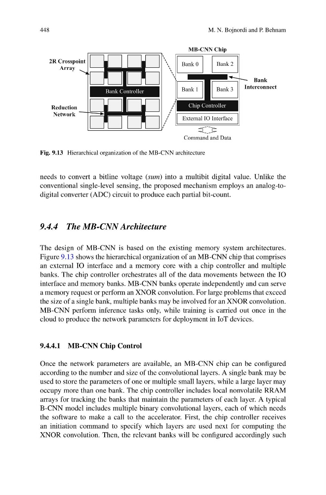
Fig. 9.13 Hierarchical organization of the MB-CNN architecture
needs to convert a bitline voltage (sum) into a multibit digital value. Unlike the
conventional single-level sensing, the proposed mechanism employs an analog-todigital converter (ADC) circuit to produce each partial bit-count.
9.4.4 The MB-CNN Architecture
The design of MB-CNN is based on the existing memory system architectures.
Figure 9.13 shows the hierarchical organization of an MB-CNN chip that comprises
an external IO interface and a memory core with a chip controller and multiple
banks. The chip controller orchestrates all of the data movements between the IO
interface and memory banks. MB-CNN banks operate independently and can serve
a memory request or perform an XNOR convolution. For large problems that exceed
the size of a single bank, multiple banks may be involved for an XNOR convolution.
MB-CNN perform inference tasks only, while training is carried out once in the
cloud to produce the network parameters for deployment in IoT devices.
9.4.4.1 MB-CNN Chip Control
Once the network parameters are available, an MB-CNN chip can be configured
according to the number and size of the convolutional layers. A single bank may be
used to store the parameters of one or multiple small layers, while a large layer may
occupy more than one bank. The chip controller includes local nonvolatile RRAM
arrays for tracking the banks that maintain the parameters of each layer. A typical
B-CNN model includes multiple binary convolutional layers, each of which needs
the software to make a call to the accelerator. First, the chip controller receives
an initiation command to specify which layers are used next for computing the
XNOR convolution. Then, the relevant banks will be configured accordingly such
M. N. Bojnordi and P. Behnam
External IO Interface
Chip Controller
Bank 0
Bank 2
Bank 1
Bank 3
MB-CNN Chip
Command and Data
Bank
Interconnect
Bank Controller
2R Crosspoint
Array
Reduction
Network
Fig. 9.13 Hierarchical organization of the MB-CNN architecture
needs to convert a bitline voltage (sum) into a multibit digital value. Unlike the
conventional single-level sensing, the proposed mechanism employs an analog-todigital converter (ADC) circuit to produce each partial bit-count.
9.4.4 The MB-CNN Architecture
The design of MB-CNN is based on the existing memory system architectures.
Figure 9.13 shows the hierarchical organization of an MB-CNN chip that comprises
an external IO interface and a memory core with a chip controller and multiple
banks. The chip controller orchestrates all of the data movements between the IO
interface and memory banks. MB-CNN banks operate independently and can serve
a memory request or perform an XNOR convolution. For large problems that exceed
the size of a single bank, multiple banks may be involved for an XNOR convolution.
MB-CNN perform inference tasks only, while training is carried out once in the
cloud to produce the network parameters for deployment in IoT devices.
9.4.4.1 MB-CNN Chip Control
Once the network parameters are available, an MB-CNN chip can be configured
according to the number and size of the convolutional layers. A single bank may be
used to store the parameters of one or multiple small layers, while a large layer may
occupy more than one bank. The chip controller includes local nonvolatile RRAM
arrays for tracking the banks that maintain the parameters of each layer. A typical
B-CNN model includes multiple binary convolutional layers, each of which needs
the software to make a call to the accelerator. First, the chip controller receives
an initiation command to specify which layers are used next for computing the
XNOR convolution. Then, the relevant banks will be configured accordingly such