

3 Engineering IoT Networks
129
End
devices
Gateway
Network
Server
Join
Server Application
Server
LoRaWAN over
LoRa RF
LoRaWAN over
backhaul network
TCP/IP
NwkSkey
AppSkey
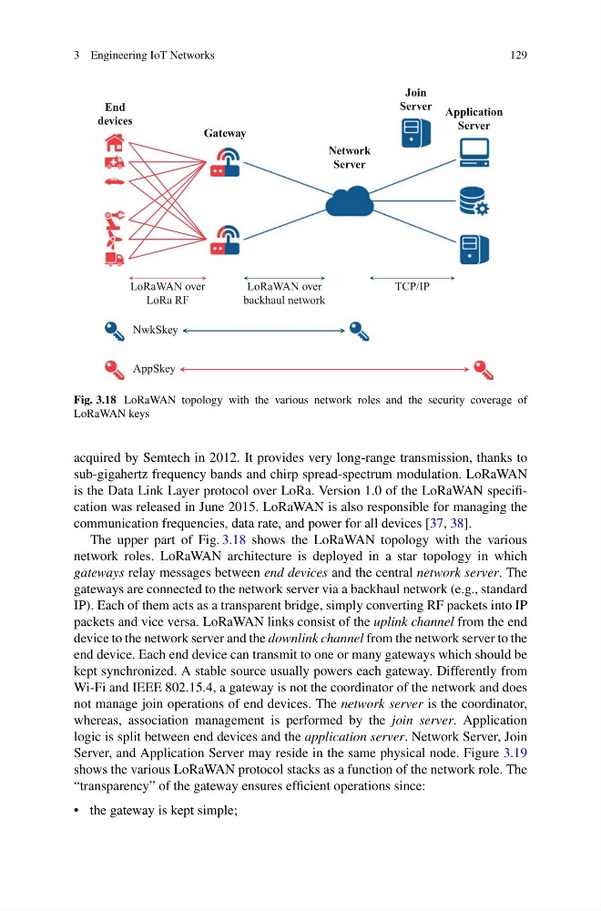
Fig. 3.18 LoRaWAN topology with the various network roles and the security coverage of
LoRaWAN keys
acquired by Semtech in 2012. It provides very long-range transmission, thanks to
sub-gigahertz frequency bands and chirp spread-spectrum modulation. LoRaWAN
is the Data Link Layer protocol over LoRa. Version 1.0 of the LoRaWAN specification was released in June 2015. LoRaWAN is also responsible for managing the
communication frequencies, data rate, and power for all devices [37, 38].
The upper part of Fig. 3.18 shows the LoRaWAN topology with the various
network roles. LoRaWAN architecture is deployed in a star topology in which
gateways relay messages between end devices and the central network server. The
gateways are connected to the network server via a backhaul network (e.g., standard
IP). Each of them acts as a transparent bridge, simply converting RF packets into IP
packets and vice versa. LoRaWAN links consist of the uplink channel from the end
device to the network server and the downlink channel from the network server to the
end device. Each end device can transmit to one or many gateways which should be
kept synchronized. A stable source usually powers each gateway. Differently from
Wi-Fi and IEEE 802.15.4, a gateway is not the coordinator of the network and does
not manage join operations of end devices. The network server is the coordinator,
whereas, association management is performed by the join server. Application
logic is split between end devices and the application server. Network Server, Join
Server, and Application Server may reside in the same physical node. Figure 3.19
shows the various LoRaWAN protocol stacks as a function of the network role. The
“transparency” of the gateway ensures efficient operations since:
• the gateway is kept simple;
129
End
devices
Gateway
Network
Server
Join
Server Application
Server
LoRaWAN over
LoRa RF
LoRaWAN over
backhaul network
TCP/IP
NwkSkey
AppSkey
Fig. 3.18 LoRaWAN topology with the various network roles and the security coverage of
LoRaWAN keys
acquired by Semtech in 2012. It provides very long-range transmission, thanks to
sub-gigahertz frequency bands and chirp spread-spectrum modulation. LoRaWAN
is the Data Link Layer protocol over LoRa. Version 1.0 of the LoRaWAN specification was released in June 2015. LoRaWAN is also responsible for managing the
communication frequencies, data rate, and power for all devices [37, 38].
The upper part of Fig. 3.18 shows the LoRaWAN topology with the various
network roles. LoRaWAN architecture is deployed in a star topology in which
gateways relay messages between end devices and the central network server. The
gateways are connected to the network server via a backhaul network (e.g., standard
IP). Each of them acts as a transparent bridge, simply converting RF packets into IP
packets and vice versa. LoRaWAN links consist of the uplink channel from the end
device to the network server and the downlink channel from the network server to the
end device. Each end device can transmit to one or many gateways which should be
kept synchronized. A stable source usually powers each gateway. Differently from
Wi-Fi and IEEE 802.15.4, a gateway is not the coordinator of the network and does
not manage join operations of end devices. The network server is the coordinator,
whereas, association management is performed by the join server. Application
logic is split between end devices and the application server. Network Server, Join
Server, and Application Server may reside in the same physical node. Figure 3.19
shows the various LoRaWAN protocol stacks as a function of the network role. The
“transparency” of the gateway ensures efficient operations since:
• the gateway is kept simple;