

11 Lithium-Ion Battery—3D Micro-/Nano-Structuring, Modification …
317
I = I 0
4
j=1
cos
k j · ·
r + φ j
+ i · sin
k j · ·
r + φ j
2
⇒
I
I 0
=
⎡
⎣
4
j=1
cos
k j · ·
r + φ j
⎤
⎦
2
+
⎡
⎣
4
j=1
sin
k j · ·
r + φ j
⎤
⎦
2
(11.1)
where
E
0
j are electric field amplitude vectors,
k j the wave vectors, and φ j the optical
phases of the interfering beams. For
r = (x, y, 0), a symmetrical arrangement of the
laser beams, and 2θ as angle between two opposite oriented laser beams, one get the
following description of the interference pattern
I
I 0
= [2 · cos(φ) · cos(−k sin(θ ) · x) + 2 · cos(−k sin(θ ) · y)]
2
+ [2 · sin(φ) · cos(−k sin(θ ) · x)]
2
(11.2)
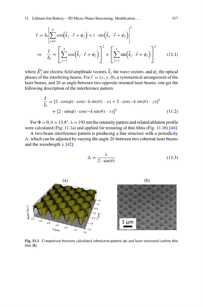
For = 0, θ = 13.8°, λ = 193 nm the intensity pattern and related ablation profile
were calculated (Fig. 11.1a) and applied for texturing of thin films (Fig. 11.1b) [44].
A two-beam interference pattern is producing a line structure with a periodicity
, which can be adjusted by varying the angle 2θ between two coherent laser beams
and the wavelength λ [42]:
=
λ
2 · sin(θ )
(11.3)
(a)
(b)
-1.5
-1.0
-0.5
0.0
0.5
1.0
1.5
-1.5
-1.0
-0.5
0.0
0.5
1.0
1.5
depth
Z
[a.u.]
Y [µ m ]
X [µ m ]
Fig. 11.1 Comparison between calculated submicron-pattern (a) and laser structured carbon thin
film (b)
317
I = I 0
4
j=1
cos
k j · ·
r + φ j
+ i · sin
k j · ·
r + φ j
2
⇒
I
I 0
=
⎡
⎣
4
j=1
cos
k j · ·
r + φ j
⎤
⎦
2
+
⎡
⎣
4
j=1
sin
k j · ·
r + φ j
⎤
⎦
2
(11.1)
where
E
0
j are electric field amplitude vectors,
k j the wave vectors, and φ j the optical
phases of the interfering beams. For
r = (x, y, 0), a symmetrical arrangement of the
laser beams, and 2θ as angle between two opposite oriented laser beams, one get the
following description of the interference pattern
I
I 0
= [2 · cos(φ) · cos(−k sin(θ ) · x) + 2 · cos(−k sin(θ ) · y)]
2
+ [2 · sin(φ) · cos(−k sin(θ ) · x)]
2
(11.2)
For = 0, θ = 13.8°, λ = 193 nm the intensity pattern and related ablation profile
were calculated (Fig. 11.1a) and applied for texturing of thin films (Fig. 11.1b) [44].
A two-beam interference pattern is producing a line structure with a periodicity
, which can be adjusted by varying the angle 2θ between two coherent laser beams
and the wavelength λ [42]:
=
λ
2 · sin(θ )
(11.3)
(a)
(b)
-1.5
-1.0
-0.5
0.0
0.5
1.0
1.5
-1.5
-1.0
-0.5
0.0
0.5
1.0
1.5
depth
Z
[a.u.]
Y [µ m ]
X [µ m ]
Fig. 11.1 Comparison between calculated submicron-pattern (a) and laser structured carbon thin
film (b)