

316
W. Pfleging et al.
amount Si on anode side are not commercialized so far because of their short operational lifetime. The formation of silicon-lithium alloys during battery operation
results in tremendous volume change of up to 300–400% in dependence on the
applied voltage window [8, 29, 36]. Failure mechanisms based on film or Si particle
cracking, Si particle pulverization, and delamination of the active layer from the
copper current collector leading to a significant drop in capacity [37, 38]. In recent
studies, it was confirmed that new binder materials, such as polyacrylic acid (PAA)
improve the adhesive force among silicon particles [39, 40]. Alternatively, chemical or topographical modification of current collector surfaces could provide an
improving of the interfacial adhesion between the composite active material and
the metallic substrate foil [41]. Prior to electrode coating processes by tape casting
or slot die coating, laser micro/nano-structuring of current collectors is performed
in order to improve the mechanical anchoring between active particles, binder, and
the metallic substrate. For laser micro-/nano-structuring of current collector surfaces
two process strategies are proposed: direct laser interference patterning (DLIP) and
laser-induced periodic surface structures (LIPSS) [41].
11.2.1 Direct Laser Interference Patterning (DLIP)
DLIP describes a very prominent method to realize micron and sub-micron patterns
by using interference-effect. Hereby, two, three, or more coherent laser beams are
superimposed in order to generate a high-intensity interference pattern along the
sample surface. In general, a single laser beam is split into two or more beams by
using beam splitters or phase shift masks, as described in [42, 43], respectively. The
number and arrangement of applied laser beams defines the submicron resolution and
type of interference pattern, e.g. intensity maxima along lines or dots for a two-beam
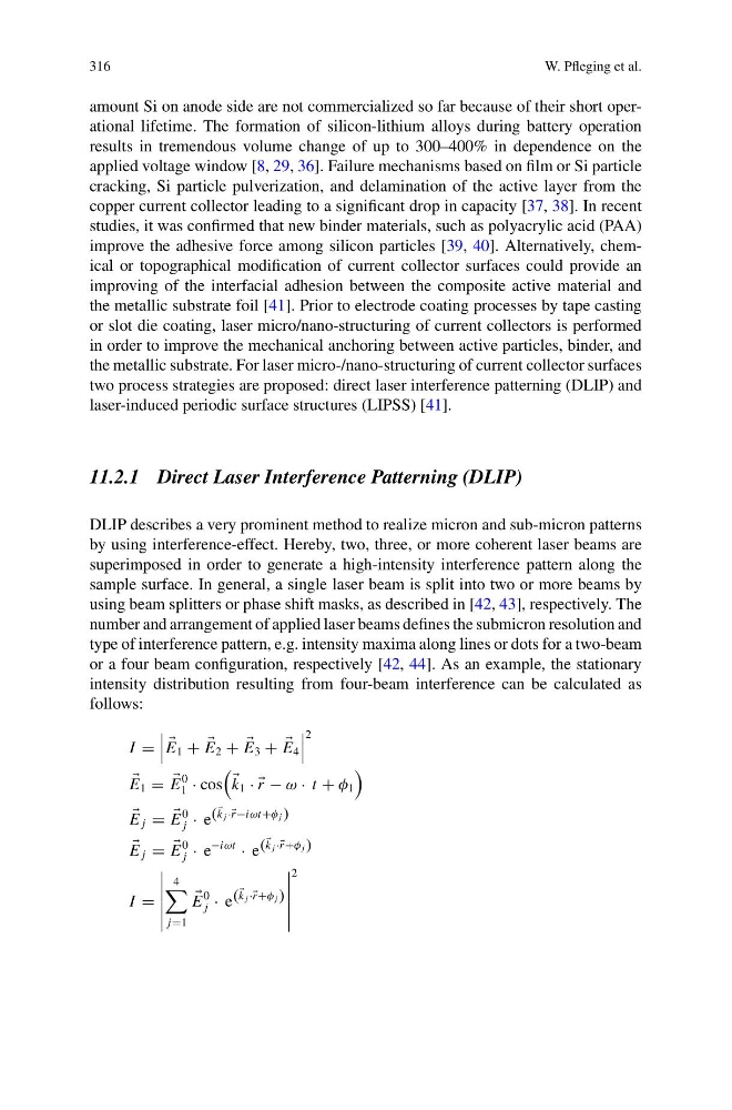
or a four beam configuration, respectively [42, 44]. As an example, the stationary
intensity distribution resulting from four-beam interference can be calculated as
follows:
I =
E 1 +
E 2 +
E 3 +
E 4
2
E 1 =
E
0
1 · cos
k 1 · ·
r − ω · t + φ 1
E j =
E
0
j · e (
k j ·· r −iωt+φ j )
E j =
E
0
j · e
−iωt
· e (
k j ·· r +φ j )
I =
4
j=1
E
0
j · e (
k j ·· r +φ j )
2
W. Pfleging et al.
amount Si on anode side are not commercialized so far because of their short operational lifetime. The formation of silicon-lithium alloys during battery operation
results in tremendous volume change of up to 300–400% in dependence on the
applied voltage window [8, 29, 36]. Failure mechanisms based on film or Si particle
cracking, Si particle pulverization, and delamination of the active layer from the
copper current collector leading to a significant drop in capacity [37, 38]. In recent
studies, it was confirmed that new binder materials, such as polyacrylic acid (PAA)
improve the adhesive force among silicon particles [39, 40]. Alternatively, chemical or topographical modification of current collector surfaces could provide an
improving of the interfacial adhesion between the composite active material and
the metallic substrate foil [41]. Prior to electrode coating processes by tape casting
or slot die coating, laser micro/nano-structuring of current collectors is performed
in order to improve the mechanical anchoring between active particles, binder, and
the metallic substrate. For laser micro-/nano-structuring of current collector surfaces
two process strategies are proposed: direct laser interference patterning (DLIP) and
laser-induced periodic surface structures (LIPSS) [41].
11.2.1 Direct Laser Interference Patterning (DLIP)
DLIP describes a very prominent method to realize micron and sub-micron patterns
by using interference-effect. Hereby, two, three, or more coherent laser beams are
superimposed in order to generate a high-intensity interference pattern along the
sample surface. In general, a single laser beam is split into two or more beams by
using beam splitters or phase shift masks, as described in [42, 43], respectively. The
number and arrangement of applied laser beams defines the submicron resolution and
type of interference pattern, e.g. intensity maxima along lines or dots for a two-beam
or a four beam configuration, respectively [42, 44]. As an example, the stationary
intensity distribution resulting from four-beam interference can be calculated as
follows:
I =
E 1 +
E 2 +
E 3 +
E 4
2
E 1 =
E
0
1 · cos
k 1 · ·
r − ω · t + φ 1
E j =
E
0
j · e (
k j ·· r −iωt+φ j )
E j =
E
0
j · e
−iωt
· e (
k j ·· r +φ j )
I =
4
j=1
E
0
j · e (
k j ·· r +φ j )
2