

264
J. Xu et al.
Fig. 8.7c (t = 0 s). After approximately 7.5 s, the polarity of the electric field was
switched (lower left image in Fig. 8.7c). The worm was then observed to rotate its
body and swim from left to right in the new direction of the electric field, clearly
demonstrating controllable electrotaxis. Furthermore, the worm continued to move
to the right at 12.5 s because the electric field remained in that direction.
8.6 Ship-in-a-Bottle Biochips
Ship-in-a-bottle integration, in which TPP is carried out in a 3D glass microfluidic
device to integrate 3D polymeric micro- and nanocomponents, is a novel technique
that can be used to enhance the functionality of microfluidic biochips. The devices
fabricated by this technique are also known as ship-in-a-bottle biochips [27, 49, 93].
The direct integration of 3D porous filters with a pore size of approximately 1 µm
into a sealed planar channel within a commercial microfluidic chip has been achieved
by TPP, allowing on-chip separation of nanoscale elements (such as dye molecules)
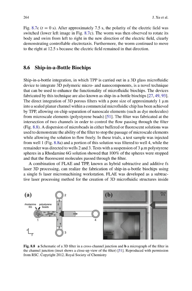
from microscale elements (polystyrene beads) [51]. The filter was fabricated at the
intersection of two channels in order to control the flow passing through the filter
(Fig. 8.8). A dispersion of microbeads in either buffered or fluorescent solutions was
used to demonstrate the ability of the filter to stop the passage of microscale elements
while allowing the solution to flow freely. In these trials, a test sample was injected
from well 1 (Fig. 8.8a) and a portion of this solution was filtered to well 4, while the
remainder was directed to wells 2 and 3. Tests with a suspension of 3 µm polystyrene
spheres in a Rhodamine 6G solution showed that 100% of the spheres were stopped
and that the fluorescent molecules passed through the filter.
A combination of FLAE and TPP, known as hybrid subtractive and additive fs
laser 3D processing, can realize the fabrication of ship-in-a-bottle biochips using
a single fs laser micromachining workstation. FLAE was developed as a subtractive laser processing method for the creation of 3D microfluidic structures inside
Fig. 8.8 a Schematic of a 3D filter in a cross-channel junction and b a micrograph of the filter in
the channel junction (inset shows a close-up view of the filter) [51]. Reproduced with permission
from RSC. Copyright 2012, Royal Society of Chemistry
J. Xu et al.
Fig. 8.7c (t = 0 s). After approximately 7.5 s, the polarity of the electric field was
switched (lower left image in Fig. 8.7c). The worm was then observed to rotate its
body and swim from left to right in the new direction of the electric field, clearly
demonstrating controllable electrotaxis. Furthermore, the worm continued to move
to the right at 12.5 s because the electric field remained in that direction.
8.6 Ship-in-a-Bottle Biochips
Ship-in-a-bottle integration, in which TPP is carried out in a 3D glass microfluidic
device to integrate 3D polymeric micro- and nanocomponents, is a novel technique
that can be used to enhance the functionality of microfluidic biochips. The devices
fabricated by this technique are also known as ship-in-a-bottle biochips [27, 49, 93].
The direct integration of 3D porous filters with a pore size of approximately 1 µm
into a sealed planar channel within a commercial microfluidic chip has been achieved
by TPP, allowing on-chip separation of nanoscale elements (such as dye molecules)
from microscale elements (polystyrene beads) [51]. The filter was fabricated at the
intersection of two channels in order to control the flow passing through the filter
(Fig. 8.8). A dispersion of microbeads in either buffered or fluorescent solutions was
used to demonstrate the ability of the filter to stop the passage of microscale elements
while allowing the solution to flow freely. In these trials, a test sample was injected
from well 1 (Fig. 8.8a) and a portion of this solution was filtered to well 4, while the
remainder was directed to wells 2 and 3. Tests with a suspension of 3 µm polystyrene
spheres in a Rhodamine 6G solution showed that 100% of the spheres were stopped
and that the fluorescent molecules passed through the filter.
A combination of FLAE and TPP, known as hybrid subtractive and additive fs
laser 3D processing, can realize the fabrication of ship-in-a-bottle biochips using
a single fs laser micromachining workstation. FLAE was developed as a subtractive laser processing method for the creation of 3D microfluidic structures inside
Fig. 8.8 a Schematic of a 3D filter in a cross-channel junction and b a micrograph of the filter in
the channel junction (inset shows a close-up view of the filter) [51]. Reproduced with permission
from RSC. Copyright 2012, Royal Society of Chemistry