

7 Micro-hole Arrays and Net-like Structure Fabrication …
237
Since the chemical etching always begins from the surface of the substrate and
progresses toward the interior of the channels, the region close to the entrance of the
channels will always suffer a longer etching period compared to the middle region.
The conical feature caused by chemical selective etching is the obstacle to realize
the homogeneous microfluidic channel system. So many researchers have devoted
to this study. Several methods have been demonstrated to fabricate homogeneous
microchannels within the substrate. (1) Drawing substrate glass after wet chemical etching [41]. The glass drawing process significantly reduces the inner surface
roughness of the fabricated channels, and a centimeter-level length of microfluidic
channels with an aspect ratio above 1000 can be realized. However, the length of the
microfluidic channel fabricated in this way is severely limited. (2) Shape-controlled
microchannels [42]. The shape control is achieved by suitable wobbling of the glass
substrate during the irradiation process, but this method increases the diameter of
the fabricated microchannel. (3) Segmented chemical etching method to fabricate
microchannels with arbitrary length and uniform diameter [43]. A segmented chemical etching method of introducing extra access ports and secondary power compensation enables the fabrication of uniform 3D helical microchannels. There are some
extra corrosion inlets on the microfluidic channel prepared by this method. (4) Fabrication of microfluidic channels using porous glass as substrate [44]. Formation of
hollow microchannels in a porous glass substrate immersed in water by FLDW and
post annealing of the glass substrate at ~1150 °C by which the porous glass can be
consolidated.
7.4.3.1 Fabricating Net-Like Hexagonal Microfluidic Channels
In the experiment, a fused silica was used as the substrate material which was cut into
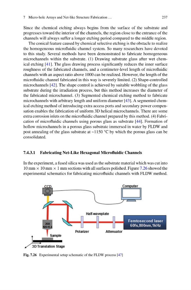
10 mm × 10 mm × 1 mm sections with all surfaces polished. Figure 7.26 showed the
experimental schematics for fabricating microfluidic channels with FLDW method.
Fig. 7.26 Experimental setup schematic of the FLDW process [47]
237
Since the chemical etching always begins from the surface of the substrate and
progresses toward the interior of the channels, the region close to the entrance of the
channels will always suffer a longer etching period compared to the middle region.
The conical feature caused by chemical selective etching is the obstacle to realize
the homogeneous microfluidic channel system. So many researchers have devoted
to this study. Several methods have been demonstrated to fabricate homogeneous
microchannels within the substrate. (1) Drawing substrate glass after wet chemical etching [41]. The glass drawing process significantly reduces the inner surface
roughness of the fabricated channels, and a centimeter-level length of microfluidic
channels with an aspect ratio above 1000 can be realized. However, the length of the
microfluidic channel fabricated in this way is severely limited. (2) Shape-controlled
microchannels [42]. The shape control is achieved by suitable wobbling of the glass
substrate during the irradiation process, but this method increases the diameter of
the fabricated microchannel. (3) Segmented chemical etching method to fabricate
microchannels with arbitrary length and uniform diameter [43]. A segmented chemical etching method of introducing extra access ports and secondary power compensation enables the fabrication of uniform 3D helical microchannels. There are some
extra corrosion inlets on the microfluidic channel prepared by this method. (4) Fabrication of microfluidic channels using porous glass as substrate [44]. Formation of
hollow microchannels in a porous glass substrate immersed in water by FLDW and
post annealing of the glass substrate at ~1150 °C by which the porous glass can be
consolidated.
7.4.3.1 Fabricating Net-Like Hexagonal Microfluidic Channels
In the experiment, a fused silica was used as the substrate material which was cut into
10 mm × 10 mm × 1 mm sections with all surfaces polished. Figure 7.26 showed the
experimental schematics for fabricating microfluidic channels with FLDW method.
Fig. 7.26 Experimental setup schematic of the FLDW process [47]