

238
G. Feng et al.
The experiment was carried out with a commercial Ti:sapphire regenerative amplifier
laser system (Legend Elite, Coherent), which generates laser pulses with center
wavelength at 800 nm, pulse duration of 60 fs, and maximum single-pulse energy
of 0.3 mJ at a repetition rate of 1 kHz. The average power of the laser beam used
to direct writing was controlled by a combination of a polarizer and a wave plate. A
x20 objective with a NA of 0.4 was employed to focus the laser beam. The sample
could be optionally translated by a PC-controlled XYZ stage (M-111.1DG, Physik
Instrumente) with a resolution of 6.9 nm. The average power of femtosecond laser
was chosen to be 160 mW, and the translating speed of the stage was 0.01 mm/s
(laser fluence was 1.27 × 10
5 J/cm
2 ). A charge-coupled device (CCD) was used for
monitoring the whole FLDW process in real time.
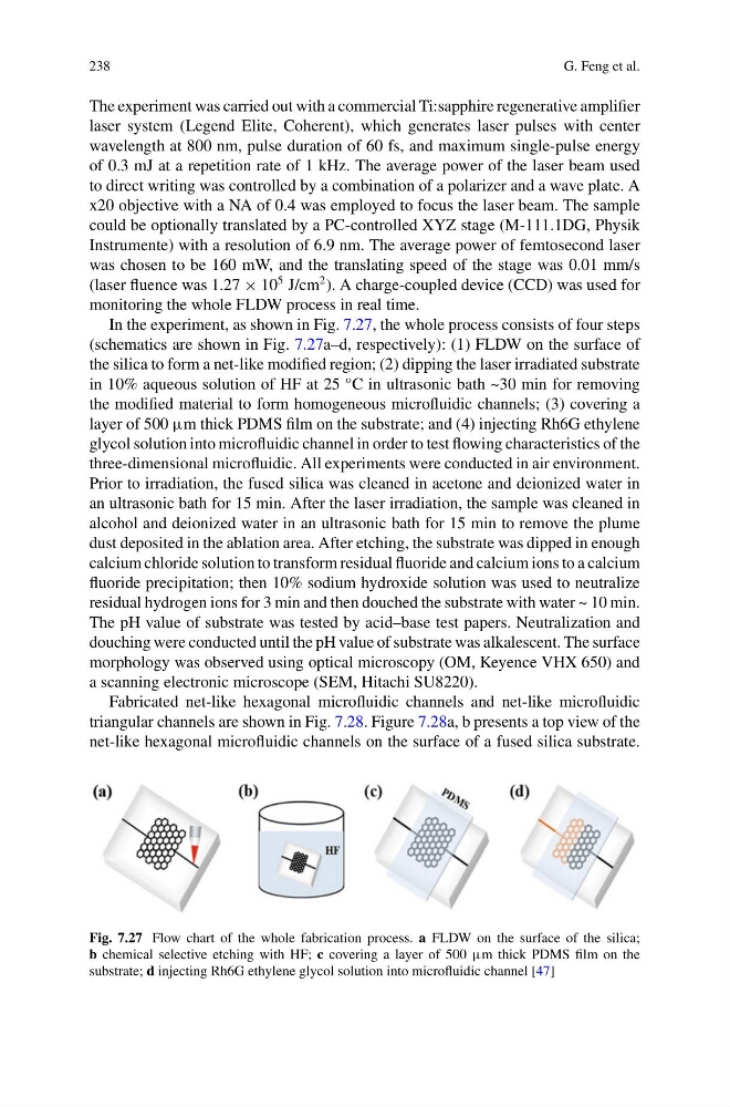
In the experiment, as shown in Fig. 7.27, the whole process consists of four steps
(schematics are shown in Fig. 7.27a–d, respectively): (1) FLDW on the surface of
the silica to form a net-like modified region; (2) dipping the laser irradiated substrate
in 10% aqueous solution of HF at 25 °C in ultrasonic bath ~30 min for removing
the modified material to form homogeneous microfluidic channels; (3) covering a
layer of 500 μm thick PDMS film on the substrate; and (4) injecting Rh6G ethylene
glycol solution into microfluidic channel in order to test flowing characteristics of the
three-dimensional microfluidic. All experiments were conducted in air environment.
Prior to irradiation, the fused silica was cleaned in acetone and deionized water in
an ultrasonic bath for 15 min. After the laser irradiation, the sample was cleaned in
alcohol and deionized water in an ultrasonic bath for 15 min to remove the plume
dust deposited in the ablation area. After etching, the substrate was dipped in enough
calcium chloride solution to transform residual fluoride and calcium ions to a calcium
fluoride precipitation; then 10% sodium hydroxide solution was used to neutralize
residual hydrogen ions for 3 min and then douched the substrate with water ~ 10 min.
The pH value of substrate was tested by acid–base test papers. Neutralization and
douching were conducted until the pH value of substrate was alkalescent. The surface
morphology was observed using optical microscopy (OM, Keyence VHX 650) and
a scanning electronic microscope (SEM, Hitachi SU8220).
Fabricated net-like hexagonal microfluidic channels and net-like microfluidic
triangular channels are shown in Fig. 7.28. Figure 7.28a, b presents a top view of the
net-like hexagonal microfluidic channels on the surface of a fused silica substrate.
Fig. 7.27 Flow chart of the whole fabrication process. a FLDW on the surface of the silica;
b chemical selective etching with HF; c covering a layer of 500 μm thick PDMS film on the
substrate; d injecting Rh6G ethylene glycol solution into microfluidic channel [47]
G. Feng et al.
The experiment was carried out with a commercial Ti:sapphire regenerative amplifier
laser system (Legend Elite, Coherent), which generates laser pulses with center
wavelength at 800 nm, pulse duration of 60 fs, and maximum single-pulse energy
of 0.3 mJ at a repetition rate of 1 kHz. The average power of the laser beam used
to direct writing was controlled by a combination of a polarizer and a wave plate. A
x20 objective with a NA of 0.4 was employed to focus the laser beam. The sample
could be optionally translated by a PC-controlled XYZ stage (M-111.1DG, Physik
Instrumente) with a resolution of 6.9 nm. The average power of femtosecond laser
was chosen to be 160 mW, and the translating speed of the stage was 0.01 mm/s
(laser fluence was 1.27 × 10
5 J/cm
2 ). A charge-coupled device (CCD) was used for
monitoring the whole FLDW process in real time.
In the experiment, as shown in Fig. 7.27, the whole process consists of four steps
(schematics are shown in Fig. 7.27a–d, respectively): (1) FLDW on the surface of
the silica to form a net-like modified region; (2) dipping the laser irradiated substrate
in 10% aqueous solution of HF at 25 °C in ultrasonic bath ~30 min for removing
the modified material to form homogeneous microfluidic channels; (3) covering a
layer of 500 μm thick PDMS film on the substrate; and (4) injecting Rh6G ethylene
glycol solution into microfluidic channel in order to test flowing characteristics of the
three-dimensional microfluidic. All experiments were conducted in air environment.
Prior to irradiation, the fused silica was cleaned in acetone and deionized water in
an ultrasonic bath for 15 min. After the laser irradiation, the sample was cleaned in
alcohol and deionized water in an ultrasonic bath for 15 min to remove the plume
dust deposited in the ablation area. After etching, the substrate was dipped in enough
calcium chloride solution to transform residual fluoride and calcium ions to a calcium
fluoride precipitation; then 10% sodium hydroxide solution was used to neutralize
residual hydrogen ions for 3 min and then douched the substrate with water ~ 10 min.
The pH value of substrate was tested by acid–base test papers. Neutralization and
douching were conducted until the pH value of substrate was alkalescent. The surface
morphology was observed using optical microscopy (OM, Keyence VHX 650) and
a scanning electronic microscope (SEM, Hitachi SU8220).
Fabricated net-like hexagonal microfluidic channels and net-like microfluidic
triangular channels are shown in Fig. 7.28. Figure 7.28a, b presents a top view of the
net-like hexagonal microfluidic channels on the surface of a fused silica substrate.
Fig. 7.27 Flow chart of the whole fabrication process. a FLDW on the surface of the silica;
b chemical selective etching with HF; c covering a layer of 500 μm thick PDMS film on the
substrate; d injecting Rh6G ethylene glycol solution into microfluidic channel [47]