

190
F. Chen and J. R. V. de Aldana
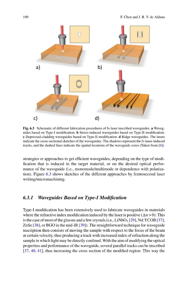
Fig. 6.3 Schematic of different fabrication procedures of fs-laser inscribed waveguides. a Waveguides based on Type-I modification. b Stress-induced waveguides based on Type-II modification.
c Depressed-cladding waveguides based on Type-II modification. d Ridge waveguides. The insets
indicate the cross-sectional sketches of the waveguides. The shadows represent the fs-laser-induced
tracks, and the dashed lines indicate the spatial locations of the waveguide cores (Taken from [6])
strategies or approaches to get efficient waveguides, depending on the type of modification that is induced in the target material, or on the desired optical performance of the waveguide (i.e., monomode/multimode or dependence with polarization). Figure 6.3 shows sketches of the different approaches by femtosecond laser
writing/micromachining.
6.3.1 Waveguides Based on Type-I Modification
Type-I modification has been extensively used to fabricate waveguides in materials
where the refractive index modification induced by the laser is positive (n > 0): This
is the case of most of the glasses and a few crystals (i.e., LiNbO 3 [29], Nd:YCOB [37],
ZnSe [38], or BGO in the mid-IR [39]). The straightforward technique for waveguide
inscription then consists of moving the sample with respect to the focus of the beam
at certain velocity, thus producing a track with increased index of refraction along the
sample in which light may be directly confined. With the aim of modifying the optical
properties and performance of the waveguide, several parallel tracks can be inscribed
[37, 40, 41], thus increasing the cross section of the modified region: This way the
F. Chen and J. R. V. de Aldana
Fig. 6.3 Schematic of different fabrication procedures of fs-laser inscribed waveguides. a Waveguides based on Type-I modification. b Stress-induced waveguides based on Type-II modification.
c Depressed-cladding waveguides based on Type-II modification. d Ridge waveguides. The insets
indicate the cross-sectional sketches of the waveguides. The shadows represent the fs-laser-induced
tracks, and the dashed lines indicate the spatial locations of the waveguide cores (Taken from [6])
strategies or approaches to get efficient waveguides, depending on the type of modification that is induced in the target material, or on the desired optical performance of the waveguide (i.e., monomode/multimode or dependence with polarization). Figure 6.3 shows sketches of the different approaches by femtosecond laser
writing/micromachining.
6.3.1 Waveguides Based on Type-I Modification
Type-I modification has been extensively used to fabricate waveguides in materials
where the refractive index modification induced by the laser is positive (n > 0): This
is the case of most of the glasses and a few crystals (i.e., LiNbO 3 [29], Nd:YCOB [37],
ZnSe [38], or BGO in the mid-IR [39]). The straightforward technique for waveguide
inscription then consists of moving the sample with respect to the focus of the beam
at certain velocity, thus producing a track with increased index of refraction along the
sample in which light may be directly confined. With the aim of modifying the optical
properties and performance of the waveguide, several parallel tracks can be inscribed
[37, 40, 41], thus increasing the cross section of the modified region: This way the