

116
I. Falcón Casas and W. Kautek
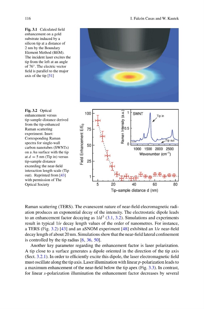
Fig. 3.1 Calculated field
enhancement on a gold
substrate induced by a
silicon tip at a distance of
2 nm by the Boundary
Element Method (BEM).
The incident laser excites the
tip from the left at an angle
of 76 ◦ . The electric vector
field is parallel to the major
axis of the tip [51]
Fig. 3.2 Optical
enhancement versus
tip-sample-distance derived
from the tip-enhanced
Raman scattering
experiment. Inset:
Corresponding Raman
spectra for single-wall
carbon nanotubes (SWNTs)
on a Au surface with the tip
at d = 5 nm (Tip in) versus
tip-sample distance
exceeding the near-field
interaction length scale (Tip
out). Reprinted from [43]
with permission of The
Optical Society
Raman scattering (TERS). The evanescent nature of near-field elecromagnetic radiation produces an exponential decay of the intensity. The electrostatic dipole leads
to an enhancement factor decaying as 1/d
3 (3.1, 3.2). Simulations and experiments
result in typical 1/e decay length values of the order of nanometres. For instance,
a TERS (Fig. 3.2) [43] and an aSNOM experiment [48] exhibited an 1/e near-field
decay length of about 20 nm. Simulations show that the near-field lateral confinement
is controlled by the tip radius [6, 36, 50].
Another key parameter regarding the enhancement factor is laser polarization.
A tip close to a surface generates a dipole oriented in the direction of the tip axis
(Sect. 3.2.1). In order to efficiently excite this dipole, the laser electromagnetic field
must oscillate along the tip axis. Laser illumination with linear p-polarization leads to
a maximum enhancement of the near-field below the tip apex (Fig. 3.3). In contrast,
for linear s-polarization illumination the enhancement factor decreases by several
I. Falcón Casas and W. Kautek
Fig. 3.1 Calculated field
enhancement on a gold
substrate induced by a
silicon tip at a distance of
2 nm by the Boundary
Element Method (BEM).
The incident laser excites the
tip from the left at an angle
of 76 ◦ . The electric vector
field is parallel to the major
axis of the tip [51]
Fig. 3.2 Optical
enhancement versus
tip-sample-distance derived
from the tip-enhanced
Raman scattering
experiment. Inset:
Corresponding Raman
spectra for single-wall
carbon nanotubes (SWNTs)
on a Au surface with the tip
at d = 5 nm (Tip in) versus
tip-sample distance
exceeding the near-field
interaction length scale (Tip
out). Reprinted from [43]
with permission of The
Optical Society
Raman scattering (TERS). The evanescent nature of near-field elecromagnetic radiation produces an exponential decay of the intensity. The electrostatic dipole leads
to an enhancement factor decaying as 1/d
3 (3.1, 3.2). Simulations and experiments
result in typical 1/e decay length values of the order of nanometres. For instance,
a TERS (Fig. 3.2) [43] and an aSNOM experiment [48] exhibited an 1/e near-field
decay length of about 20 nm. Simulations show that the near-field lateral confinement
is controlled by the tip radius [6, 36, 50].
Another key parameter regarding the enhancement factor is laser polarization.
A tip close to a surface generates a dipole oriented in the direction of the tip axis
(Sect. 3.2.1). In order to efficiently excite this dipole, the laser electromagnetic field
must oscillate along the tip axis. Laser illumination with linear p-polarization leads to
a maximum enhancement of the near-field below the tip apex (Fig. 3.3). In contrast,
for linear s-polarization illumination the enhancement factor decreases by several