

3 Apertureless Scanning Near-Field Optical Lithography
117
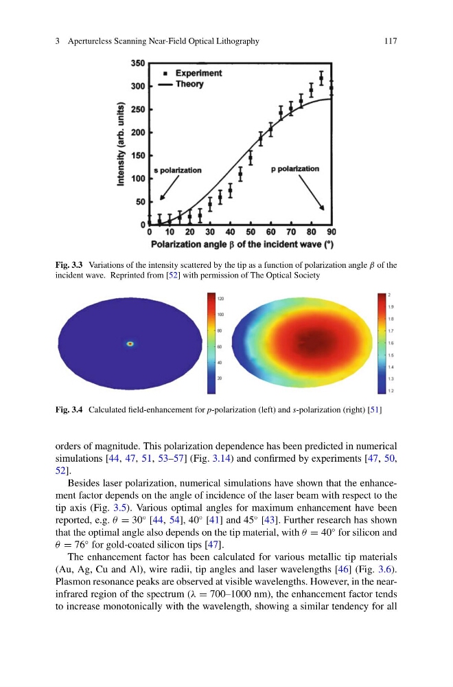
Fig. 3.3 Variations of the intensity scattered by the tip as a function of polarization angle β of the
incident wave. Reprinted from [52] with permission of The Optical Society
Fig. 3.4 Calculated field-enhancement for p-polarization (left) and s-polarization (right) [51]
orders of magnitude. This polarization dependence has been predicted in numerical
simulations [44, 47, 51, 53–57] (Fig. 3.14) and confirmed by experiments [47, 50,
52].
Besides laser polarization, numerical simulations have shown that the enhancement factor depends on the angle of incidence of the laser beam with respect to the
tip axis (Fig. 3.5). Various optimal angles for maximum enhancement have been
reported, e.g. θ = 30
◦ [44, 54], 40
◦ [41] and 45
◦ [43]. Further research has shown
that the optimal angle also depends on the tip material, with θ = 40
◦ for silicon and
θ = 76
◦ for gold-coated silicon tips [47].
The enhancement factor has been calculated for various metallic tip materials
(Au, Ag, Cu and Al), wire radii, tip angles and laser wavelengths [46] (Fig. 3.6).
Plasmon resonance peaks are observed at visible wavelengths. However, in the nearinfrared region of the spectrum (λ = 700–1000 nm), the enhancement factor tends
to increase monotonically with the wavelength, showing a similar tendency for all
117
Fig. 3.3 Variations of the intensity scattered by the tip as a function of polarization angle β of the
incident wave. Reprinted from [52] with permission of The Optical Society
Fig. 3.4 Calculated field-enhancement for p-polarization (left) and s-polarization (right) [51]
orders of magnitude. This polarization dependence has been predicted in numerical
simulations [44, 47, 51, 53–57] (Fig. 3.14) and confirmed by experiments [47, 50,
52].
Besides laser polarization, numerical simulations have shown that the enhancement factor depends on the angle of incidence of the laser beam with respect to the
tip axis (Fig. 3.5). Various optimal angles for maximum enhancement have been
reported, e.g. θ = 30
◦ [44, 54], 40
◦ [41] and 45
◦ [43]. Further research has shown
that the optimal angle also depends on the tip material, with θ = 40
◦ for silicon and
θ = 76
◦ for gold-coated silicon tips [47].
The enhancement factor has been calculated for various metallic tip materials
(Au, Ag, Cu and Al), wire radii, tip angles and laser wavelengths [46] (Fig. 3.6).
Plasmon resonance peaks are observed at visible wavelengths. However, in the nearinfrared region of the spectrum (λ = 700–1000 nm), the enhancement factor tends
to increase monotonically with the wavelength, showing a similar tendency for all