

3 Apertureless Scanning Near-Field Optical Lithography
115
retardation effects. This assumption is justified because the size of the sphere (typically 10 nm) is much smaller than the laser wavelength. Applying the method of
images, the substrate’s surface is replaced by an imaginary sphere of radius r 0 at a
distance 2(d + r 0 ) between the centres of both spheres. These two spheres form a
dipole oriented perpendicular to the surface (z direction). A linear p-polarized laser
beam, with an electromagnetic field E 0 oscillating at frequency ω, forces this dipole
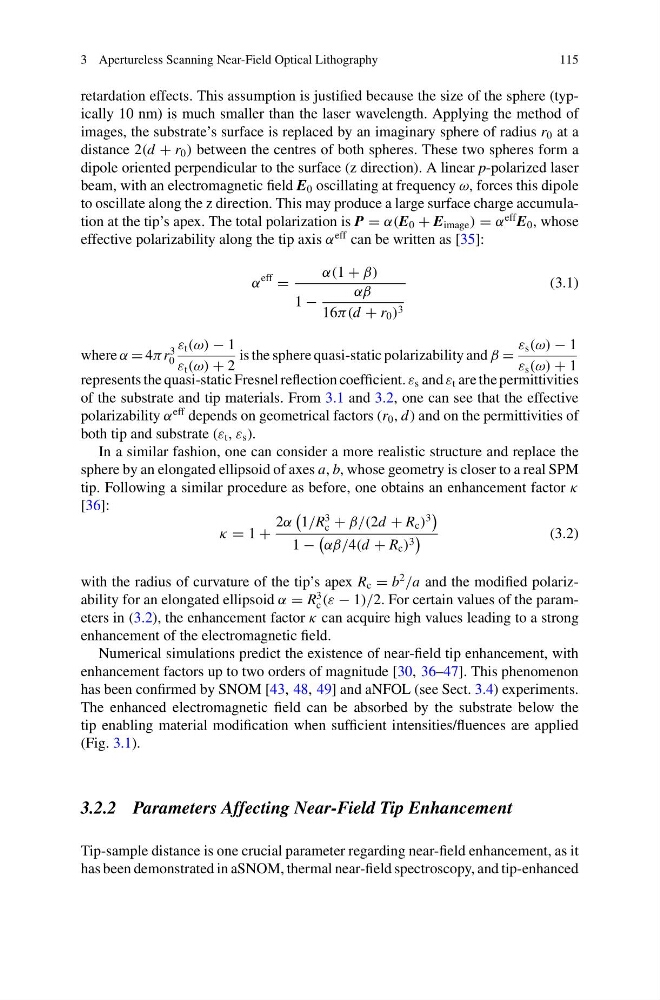
to oscillate along the z direction. This may produce a large surface charge accumulation at the tip’s apex. The total polarization is P = α(E 0 + E image ) = α
eff E 0 , whose
effective polarizability along the tip axis α
eff can be written as [35]:
α
eff
=
α(1 + β)
1 −
αβ
16π(d + r 0 ) 3
(3.1)
where α = 4π r
3
0
ε t (ω) − 1
ε t (ω) + 2
is the sphere quasi-static polarizability and β =
ε s (ω) − 1
ε s (ω) + 1
represents the quasi-static Fresnel reflection coefficient. ε s and ε t are the permittivities
of the substrate and tip materials. From 3.1 and 3.2, one can see that the effective
polarizability α
eff depends on geometrical factors (r 0 , d ) and on the permittivities of
both tip and substrate (ε t , ε s ).
In a similar fashion, one can consider a more realistic structure and replace the
sphere by an elongated ellipsoid of axes a, b, whose geometry is closer to a real SPM
tip. Following a similar procedure as before, one obtains an enhancement factor κ
[36]:
κ = 1 +
2α
1/R
3
c + β/(2d + R c )
3
1 −
αβ/4(d + R c ) 3
(3.2)
with the radius of curvature of the tip’s apex R c = b
2
/a and the modified polarizability for an elongated ellipsoid α = R
3
c (ε − 1)/2. For certain values of the parameters in (3.2), the enhancement factor κ can acquire high values leading to a strong
enhancement of the electromagnetic field.
Numerical simulations predict the existence of near-field tip enhancement, with
enhancement factors up to two orders of magnitude [30, 36–47]. This phenomenon
has been confirmed by SNOM [43, 48, 49] and aNFOL (see Sect. 3.4) experiments.
The enhanced electromagnetic field can be absorbed by the substrate below the
tip enabling material modification when sufficient intensities/fluences are applied
(Fig. 3.1).
3.2.2 Parameters Affecting Near-Field Tip Enhancement
Tip-sample distance is one crucial parameter regarding near-field enhancement, as it
has been demonstrated in aSNOM, thermal near-field spectroscopy, and tip-enhanced
115
retardation effects. This assumption is justified because the size of the sphere (typically 10 nm) is much smaller than the laser wavelength. Applying the method of
images, the substrate’s surface is replaced by an imaginary sphere of radius r 0 at a
distance 2(d + r 0 ) between the centres of both spheres. These two spheres form a
dipole oriented perpendicular to the surface (z direction). A linear p-polarized laser
beam, with an electromagnetic field E 0 oscillating at frequency ω, forces this dipole
to oscillate along the z direction. This may produce a large surface charge accumulation at the tip’s apex. The total polarization is P = α(E 0 + E image ) = α
eff E 0 , whose
effective polarizability along the tip axis α
eff can be written as [35]:
α
eff
=
α(1 + β)
1 −
αβ
16π(d + r 0 ) 3
(3.1)
where α = 4π r
3
0
ε t (ω) − 1
ε t (ω) + 2
is the sphere quasi-static polarizability and β =
ε s (ω) − 1
ε s (ω) + 1
represents the quasi-static Fresnel reflection coefficient. ε s and ε t are the permittivities
of the substrate and tip materials. From 3.1 and 3.2, one can see that the effective
polarizability α
eff depends on geometrical factors (r 0 , d ) and on the permittivities of
both tip and substrate (ε t , ε s ).
In a similar fashion, one can consider a more realistic structure and replace the
sphere by an elongated ellipsoid of axes a, b, whose geometry is closer to a real SPM
tip. Following a similar procedure as before, one obtains an enhancement factor κ
[36]:
κ = 1 +
2α
1/R
3
c + β/(2d + R c )
3
1 −
αβ/4(d + R c ) 3
(3.2)
with the radius of curvature of the tip’s apex R c = b
2
/a and the modified polarizability for an elongated ellipsoid α = R
3
c (ε − 1)/2. For certain values of the parameters in (3.2), the enhancement factor κ can acquire high values leading to a strong
enhancement of the electromagnetic field.
Numerical simulations predict the existence of near-field tip enhancement, with
enhancement factors up to two orders of magnitude [30, 36–47]. This phenomenon
has been confirmed by SNOM [43, 48, 49] and aNFOL (see Sect. 3.4) experiments.
The enhanced electromagnetic field can be absorbed by the substrate below the
tip enabling material modification when sufficient intensities/fluences are applied
(Fig. 3.1).
3.2.2 Parameters Affecting Near-Field Tip Enhancement
Tip-sample distance is one crucial parameter regarding near-field enhancement, as it
has been demonstrated in aSNOM, thermal near-field spectroscopy, and tip-enhanced