

34
3 Simulating Droplet Microfluidic Networks
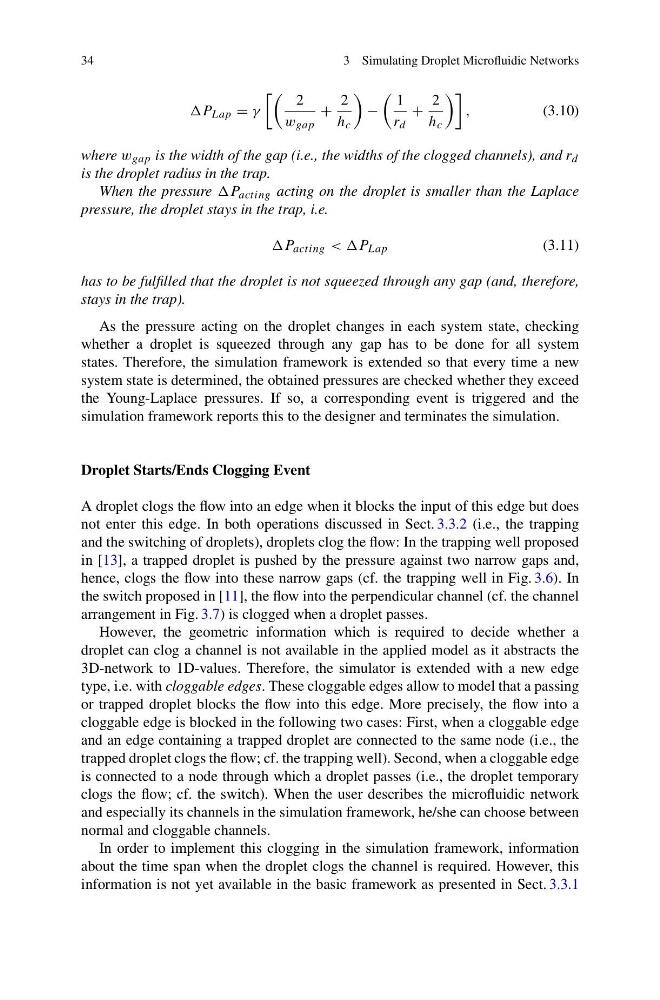
P Lap = γ
2
w gap
+
2
h c
−
1
r d
+
2
h c
,
(3.10)
where w gap is the width of the gap (i.e., the widths of the clogged channels), and r d
is the droplet radius in the trap.
When the pressure P acting acting on the droplet is smaller than the Laplace
pressure, the droplet stays in the trap, i.e.
P acting < (3.11)
has to be fulfilled that the droplet is not squeezed through any gap (and, therefore,
stays in the trap).
As the pressure acting on the droplet changes in each system state, checking
whether a droplet is squeezed through any gap has to be done for all system
states. Therefore, the simulation framework is extended so that every time a new
system state is determined, the obtained pressures are checked whether they exceed
the Young-Laplace pressures. If so, a corresponding event is triggered and the
simulation framework reports this to the designer and terminates the simulation.
Droplet Starts/Ends Clogging Event
A droplet clogs the flow into an edge when it blocks the input of this edge but does
not enter this edge. In both operations discussed in Sect. 3.3.2 (i.e., the trapping
and the switching of droplets), droplets clog the flow: In the trapping well proposed
in [13], a trapped droplet is pushed by the pressure against two narrow gaps and,
hence, clogs the flow into these narrow gaps (cf. the trapping well in Fig. 3.6). In
the switch proposed in [11], the flow into the perpendicular channel (cf. the channel
arrangement in Fig. 3.7) is clogged when a droplet passes.
However, the geometric information which is required to decide whether a
droplet can clog a channel is not available in the applied model as it abstracts the
3D-network to 1D-values. Therefore, the simulator is extended with a new edge
type, i.e. with cloggable edges. These cloggable edges allow to model that a passing
or trapped droplet blocks the flow into this edge. More precisely, the flow into a
cloggable edge is blocked in the following two cases: First, when a cloggable edge
and an edge containing a trapped droplet are connected to the same node (i.e., the
trapped droplet clogs the flow; cf. the trapping well). Second, when a cloggable edge
is connected to a node through which a droplet passes (i.e., the droplet temporary
clogs the flow; cf. the switch). When the user describes the microfluidic network
and especially its channels in the simulation framework, he/she can choose between
normal and cloggable channels.
In order to implement this clogging in the simulation framework, information
about the time span when the droplet clogs the channel is required. However, this
information is not yet available in the basic framework as presented in Sect. 3.3.1
3 Simulating Droplet Microfluidic Networks
P Lap = γ
2
w gap
+
2
h c
−
1
r d
+
2
h c
,
(3.10)
where w gap is the width of the gap (i.e., the widths of the clogged channels), and r d
is the droplet radius in the trap.
When the pressure P acting acting on the droplet is smaller than the Laplace
pressure, the droplet stays in the trap, i.e.
P acting < (3.11)
has to be fulfilled that the droplet is not squeezed through any gap (and, therefore,
stays in the trap).
As the pressure acting on the droplet changes in each system state, checking
whether a droplet is squeezed through any gap has to be done for all system
states. Therefore, the simulation framework is extended so that every time a new
system state is determined, the obtained pressures are checked whether they exceed
the Young-Laplace pressures. If so, a corresponding event is triggered and the
simulation framework reports this to the designer and terminates the simulation.
Droplet Starts/Ends Clogging Event
A droplet clogs the flow into an edge when it blocks the input of this edge but does
not enter this edge. In both operations discussed in Sect. 3.3.2 (i.e., the trapping
and the switching of droplets), droplets clog the flow: In the trapping well proposed
in [13], a trapped droplet is pushed by the pressure against two narrow gaps and,
hence, clogs the flow into these narrow gaps (cf. the trapping well in Fig. 3.6). In
the switch proposed in [11], the flow into the perpendicular channel (cf. the channel
arrangement in Fig. 3.7) is clogged when a droplet passes.
However, the geometric information which is required to decide whether a
droplet can clog a channel is not available in the applied model as it abstracts the
3D-network to 1D-values. Therefore, the simulator is extended with a new edge
type, i.e. with cloggable edges. These cloggable edges allow to model that a passing
or trapped droplet blocks the flow into this edge. More precisely, the flow into a
cloggable edge is blocked in the following two cases: First, when a cloggable edge
and an edge containing a trapped droplet are connected to the same node (i.e., the
trapped droplet clogs the flow; cf. the trapping well). Second, when a cloggable edge
is connected to a node through which a droplet passes (i.e., the droplet temporary
clogs the flow; cf. the switch). When the user describes the microfluidic network
and especially its channels in the simulation framework, he/she can choose between
normal and cloggable channels.
In order to implement this clogging in the simulation framework, information
about the time span when the droplet clogs the channel is required. However, this
information is not yet available in the basic framework as presented in Sect. 3.3.1