

3.3 Advanced Simulation Framework
35
2
1
c 3
Start of clogging
c
c
Flow 0 µl/min
"Tail"
"Head"
Stop of clogging
1
c 3
c 2
c
Flow> 0 µl/min
"Tail"
"Head"
(a) Start of clogging
(b) End of clogging
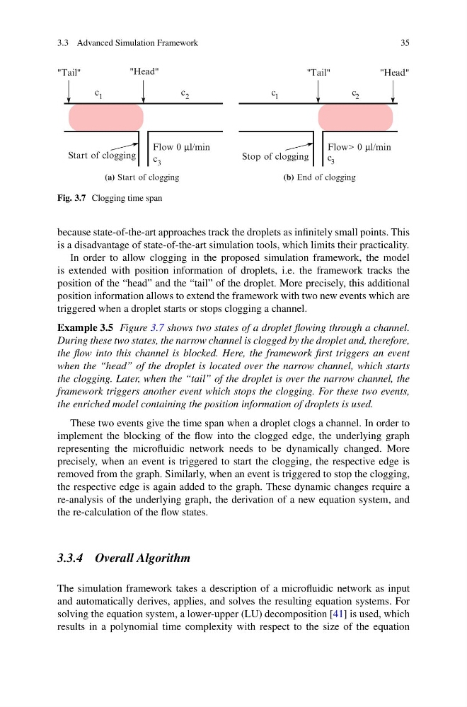
Fig. 3.7 Clogging time span
because state-of-the-art approaches track the droplets as infinitely small points. This
is a disadvantage of state-of-the-art simulation tools, which limits their practicality.
In order to allow clogging in the proposed simulation framework, the model
is extended with position information of droplets, i.e. the framework tracks the
position of the “head” and the “tail” of the droplet. More precisely, this additional
position information allows to extend the framework with two new events which are
triggered when a droplet starts or stops clogging a channel.
Example 3.5 Figure 3.7 shows two states of a droplet flowing through a channel.
During these two states, the narrow channel is clogged by the droplet and, therefore,
the flow into this channel is blocked. Here, the framework first triggers an event
when the “head” of the droplet is located over the narrow channel, which starts
the clogging. Later, when the “tail” of the droplet is over the narrow channel, the
framework triggers another event which stops the clogging. For these two events,
the enriched model containing the position information of droplets is used.
These two events give the time span when a droplet clogs a channel. In order to
implement the blocking of the flow into the clogged edge, the underlying graph
representing the microfluidic network needs to be dynamically changed. More
precisely, when an event is triggered to start the clogging, the respective edge is
removed from the graph. Similarly, when an event is triggered to stop the clogging,
the respective edge is again added to the graph. These dynamic changes require a
re-analysis of the underlying graph, the derivation of a new equation system, and
the re-calculation of the flow states.
3.3.4 Overall Algorithm
The simulation framework takes a description of a microfluidic network as input
and automatically derives, applies, and solves the resulting equation systems. For
solving the equation system, a lower-upper (LU) decomposition [41] is used, which
results in a polynomial time complexity with respect to the size of the equation
35
2
1
c 3
Start of clogging
c
c
Flow 0 µl/min
"Tail"
"Head"
Stop of clogging
1
c 3
c 2
c
Flow> 0 µl/min
"Tail"
"Head"
(a) Start of clogging
(b) End of clogging
Fig. 3.7 Clogging time span
because state-of-the-art approaches track the droplets as infinitely small points. This
is a disadvantage of state-of-the-art simulation tools, which limits their practicality.
In order to allow clogging in the proposed simulation framework, the model
is extended with position information of droplets, i.e. the framework tracks the
position of the “head” and the “tail” of the droplet. More precisely, this additional
position information allows to extend the framework with two new events which are
triggered when a droplet starts or stops clogging a channel.
Example 3.5 Figure 3.7 shows two states of a droplet flowing through a channel.
During these two states, the narrow channel is clogged by the droplet and, therefore,
the flow into this channel is blocked. Here, the framework first triggers an event
when the “head” of the droplet is located over the narrow channel, which starts
the clogging. Later, when the “tail” of the droplet is over the narrow channel, the
framework triggers another event which stops the clogging. For these two events,
the enriched model containing the position information of droplets is used.
These two events give the time span when a droplet clogs a channel. In order to
implement the blocking of the flow into the clogged edge, the underlying graph
representing the microfluidic network needs to be dynamically changed. More
precisely, when an event is triggered to start the clogging, the respective edge is
removed from the graph. Similarly, when an event is triggered to stop the clogging,
the respective edge is again added to the graph. These dynamic changes require a
re-analysis of the underlying graph, the derivation of a new equation system, and
the re-calculation of the flow states.
3.3.4 Overall Algorithm
The simulation framework takes a description of a microfluidic network as input
and automatically derives, applies, and solves the resulting equation systems. For
solving the equation system, a lower-upper (LU) decomposition [41] is used, which
results in a polynomial time complexity with respect to the size of the equation