

26
3 Simulating Droplet Microfluidic Networks
Similarly, for systems with water-in-oil droplets having a low Capillary number
and a small ratio between the dispersed and the continuous phase (i.e., Ca < 0.01
and μ disp /μ cont < 0.1), the viscosity of droplets can be neglected. In this case,
each droplet increases the resistance of the segment of a channel it occupies by 2–5
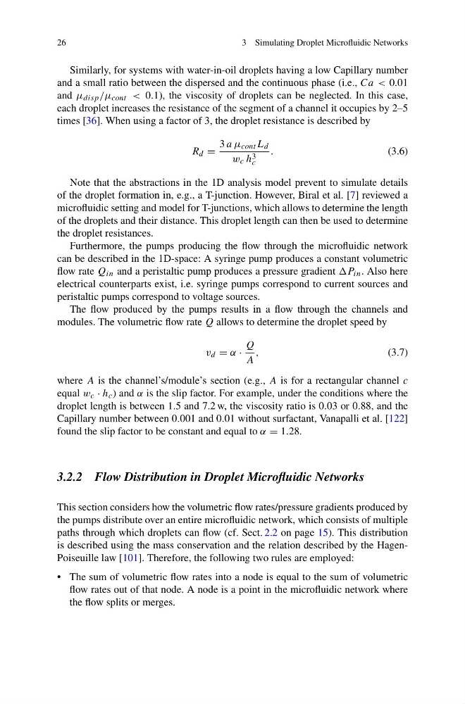
times [36]. When using a factor of 3, the droplet resistance is described by
R d =
3 a μ cont L d
w c h 3
c
.
(3.6)
Note that the abstractions in the 1D analysis model prevent to simulate details
of the droplet formation in, e.g., a T-junction. However, Biral et al. [7] reviewed a
microfluidic setting and model for T-junctions, which allows to determine the length
of the droplets and their distance. This droplet length can then be used to determine
the droplet resistances.
Furthermore, the pumps producing the flow through the microfluidic network
can be described in the 1D-space: A syringe pump produces a constant volumetric
flow rate Q in and a peristaltic pump produces a pressure gradient P in . Also here
electrical counterparts exist, i.e. syringe pumps correspond to current sources and
peristaltic pumps correspond to voltage sources.
The flow produced by the pumps results in a flow through the channels and
modules. The volumetric flow rate Q allows to determine the droplet speed by
v d = α ·
Q
A
,
(3.7)
where A is the channel’s/module’s section (e.g., A is for a rectangular channel c
equal w c · h c ) and α is the slip factor. For example, under the conditions where the
droplet length is between 1.5 and 7.2 w, the viscosity ratio is 0.03 or 0.88, and the
Capillary number between 0.001 and 0.01 without surfactant, Vanapalli et al. [122]
found the slip factor to be constant and equal to α = 1.28.
3.2.2 Flow Distribution in Droplet Microfluidic Networks
This section considers how the volumetric flow rates/pressure gradients produced by
the pumps distribute over an entire microfluidic network, which consists of multiple
paths through which droplets can flow (cf. Sect. 2.2 on page 15). This distribution
is described using the mass conservation and the relation described by the HagenPoiseuille law [101]. Therefore, the following two rules are employed:
• The sum of volumetric flow rates into a node is equal to the sum of volumetric
flow rates out of that node. A node is a point in the microfluidic network where
the flow splits or merges.
3 Simulating Droplet Microfluidic Networks
Similarly, for systems with water-in-oil droplets having a low Capillary number
and a small ratio between the dispersed and the continuous phase (i.e., Ca < 0.01
and μ disp /μ cont < 0.1), the viscosity of droplets can be neglected. In this case,
each droplet increases the resistance of the segment of a channel it occupies by 2–5
times [36]. When using a factor of 3, the droplet resistance is described by
R d =
3 a μ cont L d
w c h 3
c
.
(3.6)
Note that the abstractions in the 1D analysis model prevent to simulate details
of the droplet formation in, e.g., a T-junction. However, Biral et al. [7] reviewed a
microfluidic setting and model for T-junctions, which allows to determine the length
of the droplets and their distance. This droplet length can then be used to determine
the droplet resistances.
Furthermore, the pumps producing the flow through the microfluidic network
can be described in the 1D-space: A syringe pump produces a constant volumetric
flow rate Q in and a peristaltic pump produces a pressure gradient P in . Also here
electrical counterparts exist, i.e. syringe pumps correspond to current sources and
peristaltic pumps correspond to voltage sources.
The flow produced by the pumps results in a flow through the channels and
modules. The volumetric flow rate Q allows to determine the droplet speed by
v d = α ·
Q
A
,
(3.7)
where A is the channel’s/module’s section (e.g., A is for a rectangular channel c
equal w c · h c ) and α is the slip factor. For example, under the conditions where the
droplet length is between 1.5 and 7.2 w, the viscosity ratio is 0.03 or 0.88, and the
Capillary number between 0.001 and 0.01 without surfactant, Vanapalli et al. [122]
found the slip factor to be constant and equal to α = 1.28.
3.2.2 Flow Distribution in Droplet Microfluidic Networks
This section considers how the volumetric flow rates/pressure gradients produced by
the pumps distribute over an entire microfluidic network, which consists of multiple
paths through which droplets can flow (cf. Sect. 2.2 on page 15). This distribution
is described using the mass conservation and the relation described by the HagenPoiseuille law [101]. Therefore, the following two rules are employed:
• The sum of volumetric flow rates into a node is equal to the sum of volumetric
flow rates out of that node. A node is a point in the microfluidic network where
the flow splits or merges.