

7 The Crystalline Solid—Dislocations
63
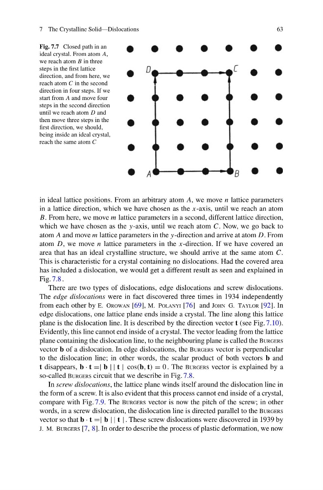
Fig. 7.7 Closed path in an
ideal crystal. From atom A,
we reach atom B in three
steps in the first lattice
direction, and from here, we
reach atom C in the second
direction in four steps. If we
start from A and move four
steps in the second direction
until we reach atom D and
then move three steps in the
first direction, we should,
being inside an ideal crystal,
reach the same atom C
in ideal lattice positions. From an arbitrary atom A, we move n lattice parameters
in a lattice direction, which we have chosen as the x-axis, until we reach an atom
B. From here, we move m lattice parameters in a second, different lattice direction,
which we have chosen as the y-axis, until we reach atom C. Now, we go back to
atom A and move m lattice parameters in the y-direction and arrive at atom D. From
atom D, we move n lattice parameters in the x-direction. If we have covered an
area that has an ideal crystalline structure, we should arrive at the same atom C.
This is characteristic for a crystal containing no dislocations. Had the covered area
has included a dislocation, we would get a different result as seen and explained in
Fig. 7.8 .
There are two types of dislocations, edge dislocations and screw dislocations.
The edge dislocations were in fact discovered three times in 1934 independently
from each other by E. Orowan [69], M. Polanyi [76] and John G. Taylor [92]. In
edge dislocations, one lattice plane ends inside a crystal. The line along this lattice
plane is the dislocation line. It is described by the direction vector t (see Fig. 7.10).
Evidently, this line cannot end inside of a crystal. The vector leading from the lattice
plane containing the dislocation line, to the neighbouring plane is called the Burgers
vector b of a dislocation. In edge dislocations, the Burgers vector is perpendicular
to the dislocation line; in other words, the scalar product of both vectors b and
t disappears, b · t =| b | | t | cos(b, t) = 0 . The Burgers vector is explained by a
so-called Burgers circuit that we describe in Fig. 7.8.
In screw dislocations, the lattice plane winds itself around the dislocation line in
the form of a screw. It is also evident that this process cannot end inside of a crystal,
compare with Fig. 7.9. The Burgers vector is now the pitch of the screw; in other
words, in a screw dislocation, the dislocation line is directed parallel to the Burgers
vector so that b · t =| b | | t | . These screw dislocations were discovered in 1939 by
J. M. Burgers [7, 8]. In order to describe the process of plastic deformation, we now
63
Fig. 7.7 Closed path in an
ideal crystal. From atom A,
we reach atom B in three
steps in the first lattice
direction, and from here, we
reach atom C in the second
direction in four steps. If we
start from A and move four
steps in the second direction
until we reach atom D and
then move three steps in the
first direction, we should,
being inside an ideal crystal,
reach the same atom C
in ideal lattice positions. From an arbitrary atom A, we move n lattice parameters
in a lattice direction, which we have chosen as the x-axis, until we reach an atom
B. From here, we move m lattice parameters in a second, different lattice direction,
which we have chosen as the y-axis, until we reach atom C. Now, we go back to
atom A and move m lattice parameters in the y-direction and arrive at atom D. From
atom D, we move n lattice parameters in the x-direction. If we have covered an
area that has an ideal crystalline structure, we should arrive at the same atom C.
This is characteristic for a crystal containing no dislocations. Had the covered area
has included a dislocation, we would get a different result as seen and explained in
Fig. 7.8 .
There are two types of dislocations, edge dislocations and screw dislocations.
The edge dislocations were in fact discovered three times in 1934 independently
from each other by E. Orowan [69], M. Polanyi [76] and John G. Taylor [92]. In
edge dislocations, one lattice plane ends inside a crystal. The line along this lattice
plane is the dislocation line. It is described by the direction vector t (see Fig. 7.10).
Evidently, this line cannot end inside of a crystal. The vector leading from the lattice
plane containing the dislocation line, to the neighbouring plane is called the Burgers
vector b of a dislocation. In edge dislocations, the Burgers vector is perpendicular
to the dislocation line; in other words, the scalar product of both vectors b and
t disappears, b · t =| b | | t | cos(b, t) = 0 . The Burgers vector is explained by a
so-called Burgers circuit that we describe in Fig. 7.8.
In screw dislocations, the lattice plane winds itself around the dislocation line in
the form of a screw. It is also evident that this process cannot end inside of a crystal,
compare with Fig. 7.9. The Burgers vector is now the pitch of the screw; in other
words, in a screw dislocation, the dislocation line is directed parallel to the Burgers
vector so that b · t =| b | | t | . These screw dislocations were discovered in 1939 by
J. M. Burgers [7, 8]. In order to describe the process of plastic deformation, we now