

74
Electrochemical Supercapacitors for Energy Storage and Delivery
⎛
E
V
o
⎞
ER
⎛ R + R ⎞
i cell = −
+ ⎜ ⎜ sc −
p
⎟ exp ⎜ −
esr
p t ⎟
R p + R
⎜
⎟
⎜
T ⎟
esr
+
⎝ R
C
esr
R esr ( R esr R p ) ⎠ ⎝ R R
esr p dl ⎠
(2.54)
(Discha arging process)
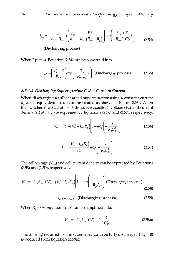
When Rp → ∞, Equation (2.54) can be converted into:
⎛ V
o
⎞
⎛
sc − E
R
⎞
i cell = ⎜ ⎜
⎟ ⎟ exp⎜ ⎜−
esr
ischarging
T
t⎟ (D
process)
(2.55)
⎝ R esr ⎠
⎝ R C
esr dl ⎠
2.5.4.5 Discharging Supercapacitor Cell at Constant Current
When discharging a fully charged supercapacitor using a constant current
(I cell ), the equivalent circuit can be treated as shown in Figure 2.16c. When
the switcher is closed at t = 0, the supercapacitor’s voltage (V sc ) and current
density (i sc ) at t ≥ 0 are expressed by Equations (2.56) and (2.57), respectively:
(
)
⎡
⎛
⎞⎤
V
o
t
sc − V
o
sc = V
sc + I cell R p ⎢ 1 e
− xp ⎜ −
⎟⎥
T
(2.56)
⎜
⎟ ⎟
⎢
R C
p d ⎥
⎣
⎝
l ⎠⎦
V
o
⎛
sc + I cell R p
⎞
t
i sc =
(
) exp ⎜ − ⎟
(2.57)
R
⎜
⎟
p
⎝ R C
T
p dl ⎠
The cell voltage (V cell ) and cell current density can be expressed by Equations
(2.58) and (2.59), respectively:
(
⎡
⎛
⎞⎤
t
V
I
o
o
cell = − cell R esr + V sc − V sc + I R
cell p ) ⎢ 1 e
− xp ⎜ −
⎟⎥
T
(Discharging process) )
⎜
⎟
⎢ ⎣
⎝ R R C
p dl ⎠ ⎥ ⎦
(2.58)
i cell = –I cell (Discharging process)
(2.59)
When R p → ∞, Equation (2.58) can be simplified into:
t
V c ell = −I cell R esr + V
o
sc − I cell
(2.58a)
C
T
dl
The time (t fd ) required for the supercapacitor to be fully discharged (V cell = 0)
is deduced from Equation (2.58a):
Electrochemical Supercapacitors for Energy Storage and Delivery
⎛
E
V
o
⎞
ER
⎛ R + R ⎞
i cell = −
+ ⎜ ⎜ sc −
p
⎟ exp ⎜ −
esr
p t ⎟
R p + R
⎜
⎟
⎜
T ⎟
esr
+
⎝ R
C
esr
R esr ( R esr R p ) ⎠ ⎝ R R
esr p dl ⎠
(2.54)
(Discha arging process)
When Rp → ∞, Equation (2.54) can be converted into:
⎛ V
o
⎞
⎛
sc − E
R
⎞
i cell = ⎜ ⎜
⎟ ⎟ exp⎜ ⎜−
esr
ischarging
T
t⎟ (D
process)
(2.55)
⎝ R esr ⎠
⎝ R C
esr dl ⎠
2.5.4.5 Discharging Supercapacitor Cell at Constant Current
When discharging a fully charged supercapacitor using a constant current
(I cell ), the equivalent circuit can be treated as shown in Figure 2.16c. When
the switcher is closed at t = 0, the supercapacitor’s voltage (V sc ) and current
density (i sc ) at t ≥ 0 are expressed by Equations (2.56) and (2.57), respectively:
(
)
⎡
⎛
⎞⎤
V
o
t
sc − V
o
sc = V
sc + I cell R p ⎢ 1 e
− xp ⎜ −
⎟⎥
T
(2.56)
⎜
⎟ ⎟
⎢
R C
p d ⎥
⎣
⎝
l ⎠⎦
V
o
⎛
sc + I cell R p
⎞
t
i sc =
(
) exp ⎜ − ⎟
(2.57)
R
⎜
⎟
p
⎝ R C
T
p dl ⎠
The cell voltage (V cell ) and cell current density can be expressed by Equations
(2.58) and (2.59), respectively:
(
⎡
⎛
⎞⎤
t
V
I
o
o
cell = − cell R esr + V sc − V sc + I R
cell p ) ⎢ 1 e
− xp ⎜ −
⎟⎥
T
(Discharging process) )
⎜
⎟
⎢ ⎣
⎝ R R C
p dl ⎠ ⎥ ⎦
(2.58)
i cell = –I cell (Discharging process)
(2.59)
When R p → ∞, Equation (2.58) can be simplified into:
t
V c ell = −I cell R esr + V
o
sc − I cell
(2.58a)
C
T
dl
The time (t fd ) required for the supercapacitor to be fully discharged (V cell = 0)
is deduced from Equation (2.58a):