

73
Fundamentals of Electrochemical Double-Layer Supercapacitors
=
o
⎛
R
⎞
⎛
⎞
esr
R
V
V
p + R esr + R L
cell
sc − i cell R esr = V sc ⎜1−
⎟e exp ⎜ −
t ⎟
⎜
⎟
⎝ R + R ⎠
⎝ R R
T
esr
L
p ( esr + R L ) C dl ⎠ (2.48)
(Disc charging process)
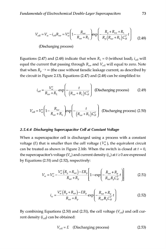
Equations (2.47) and (2.48) indicate that when R L = 0 (without load), i cell will
equal the current that passing through R esr and V cell will equal to zero. Note
that when R p → ∞ (the case without faradic leakage current, as described by
the circuit in Figure 2.13), Equations (2.47) and (2.48) can be simplified to:
⎛
⎞
V
o
t
i
sc
cell =
exp ⎜ −
⎟
(
)
T
( (Discharging process)
(2.49)
R + R L
⎜
esr
⎝ R esr + R L C ⎟
dl ⎠
⎛
⎞
⎞
R
⎛
t
V cell = V
o
esr
sc ⎜1−
⎟exp ⎜ −
⎟ (Discharging process) (2.50)
⎝ R esr + R L
⎜
⎠
⎝ ( R + R
T ⎟
esr
L ) C C dl ⎠
2.5.4.4 Discharging Supercapacitor Cell at Constant Voltage
When a supercapacitor cell is discharged using a process with a constant
voltage (E) that is smaller than the cell voltage ( V
o
sc ), the equivalent circuit
can be treated as shown in Figure 2.16b. When the switch is closed at t = 0,
the supercapacitor’s voltage (V sc ) and current density (i sc ) at t ≥ 0 are expressed
by Equations (2.51) and (2.52), respectively:
o
V R
o
sc ( p + R ) − ER ⎡
⎛ R + + R ⎞⎤
V
esr
p
sc = V sc −
⎢ 1 e
− xp ⎜ −
esr
p t ⎟⎥
(2.51)
⎜
R
⎟
esr + R p
⎢ ⎣
⎝ R R
esr p C
T
dl ⎠ ⎥ ⎦
V R
o
sc ( p + R esr ) − ER ⎛
⎞
i =
p
R
R
−
esr + p
sc
exp ⎜
t ⎟
(2.52)
R
R
⎜
esr
⎝
⎟
+
R R
T
p
esr R C
p dl ⎠
By combining Equations (2.50) and (2.51), the cell voltage (V cell ) and cell current density (i cell ) can be obtained:
V cell = E (Discharging process)
(2.53)
Fundamentals of Electrochemical Double-Layer Supercapacitors
=
o
⎛
R
⎞
⎛
⎞
esr
R
V
V
p + R esr + R L
cell
sc − i cell R esr = V sc ⎜1−
⎟e exp ⎜ −
t ⎟
⎜
⎟
⎝ R + R ⎠
⎝ R R
T
esr
L
p ( esr + R L ) C dl ⎠ (2.48)
(Disc charging process)
Equations (2.47) and (2.48) indicate that when R L = 0 (without load), i cell will
equal the current that passing through R esr and V cell will equal to zero. Note
that when R p → ∞ (the case without faradic leakage current, as described by
the circuit in Figure 2.13), Equations (2.47) and (2.48) can be simplified to:
⎛
⎞
V
o
t
i
sc
cell =
exp ⎜ −
⎟
(
)
T
( (Discharging process)
(2.49)
R + R L
⎜
esr
⎝ R esr + R L C ⎟
dl ⎠
⎛
⎞
⎞
R
⎛
t
V cell = V
o
esr
sc ⎜1−
⎟exp ⎜ −
⎟ (Discharging process) (2.50)
⎝ R esr + R L
⎜
⎠
⎝ ( R + R
T ⎟
esr
L ) C C dl ⎠
2.5.4.4 Discharging Supercapacitor Cell at Constant Voltage
When a supercapacitor cell is discharged using a process with a constant
voltage (E) that is smaller than the cell voltage ( V
o
sc ), the equivalent circuit
can be treated as shown in Figure 2.16b. When the switch is closed at t = 0,
the supercapacitor’s voltage (V sc ) and current density (i sc ) at t ≥ 0 are expressed
by Equations (2.51) and (2.52), respectively:
o
V R
o
sc ( p + R ) − ER ⎡
⎛ R + + R ⎞⎤
V
esr
p
sc = V sc −
⎢ 1 e
− xp ⎜ −
esr
p t ⎟⎥
(2.51)
⎜
R
⎟
esr + R p
⎢ ⎣
⎝ R R
esr p C
T
dl ⎠ ⎥ ⎦
V R
o
sc ( p + R esr ) − ER ⎛
⎞
i =
p
R
R
−
esr + p
sc
exp ⎜
t ⎟
(2.52)
R
R
⎜
esr
⎝
⎟
+
R R
T
p
esr R C
p dl ⎠
By combining Equations (2.50) and (2.51), the cell voltage (V cell ) and cell current density (i cell ) can be obtained:
V cell = E (Discharging process)
(2.53)