

72
Electrochemical Supercapacitors for Energy Storage and Delivery
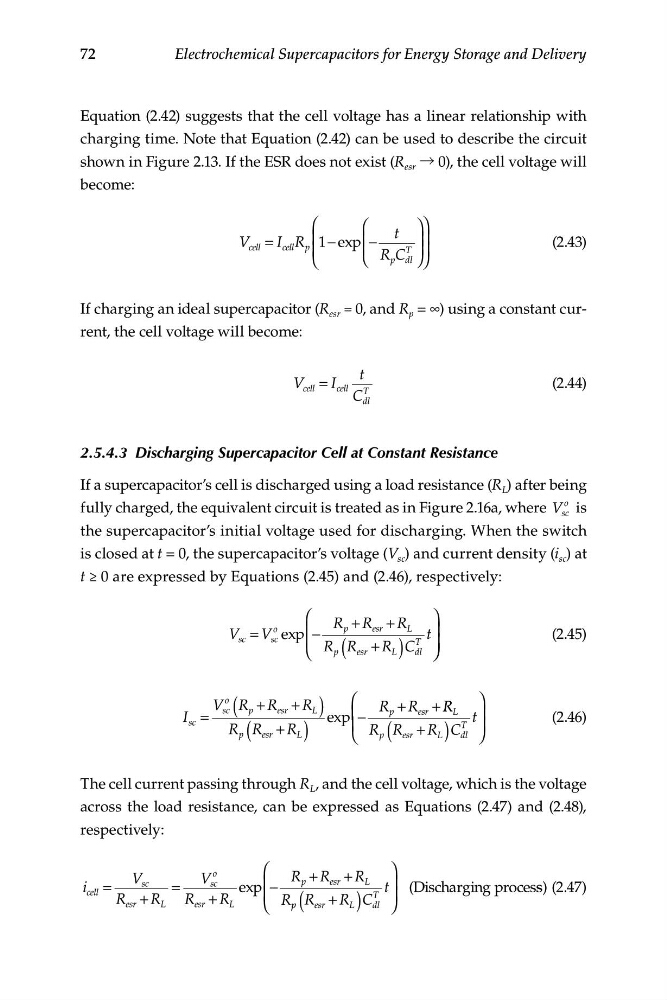
Equation (2.42) suggests that the cell voltage has a linear relationship with
charging time. Note that Equation (2.42) can be used to describe the circuit
shown in Figure 2.13. If the ESR does not exist (R esr → 0), the cell voltage will
become:
⎛
⎛
⎞⎞
t
V cell = I cell R p ⎜ 1 e
− xp ⎜ −
⎟⎟
(2.43)
⎜
⎜
T ⎟⎟
⎝
⎝ R C
p dl ⎠⎠
If charging an ideal supercapacitor (R esr = 0, and R p = ∞) using a constant current, the cell voltage will become:
t
V ce ll = I cell T
(2.44)
C dl
2.5.4.3 Discharging Supercapacitor Cell at Constant Resistance
If a supercapacitor’s cell is discharged using a load resistance (R L ) after being
fully charged, the equivalent circuit is treated as in Figure 2.16a, where V
o
sc is
the supercapacitor’s initial voltage used for discharging. When the switch
is closed at t = 0, the supercapacitor’s voltage (V sc ) and current density (i sc ) at
t ≥ 0 are expressed by Equations (2.45) and (2.46), respectively:
⎛
⎞
R + R + R
V sc = V
o exp ⎜ −
p
esr
L
sc
t ⎟
(2.45)
⎜
⎝ R R
p
T
+ R
⎟
( esr L ) C dl ⎠ ⎠
V R
o
⎛
⎞
I =
sc
+ R esr + R L
sc
( p
)
R + R esr + R R
exp ⎜ −
p
L
t ⎟
)
(2
p (
.46)
R R esr + R L
⎜ R R
C
T ⎟
+
⎝ p ( esr R L ) dl ⎠
The cell current passing through R L , and the cell voltage, which is the voltage
across the load resistance, can be expressed as Equations (2.47) and (2.48),
respectively:
o
⎛
⎞
V
V
R + R +
sc
sc
R
i cell =
=
exp ⎜ −
⎟
R + R
R + R
⎜
esr
L
esr
L
⎝ R p p (
p
esr
)
L
t (Discharging
s
R
T
process) (2.47)
⎟
esr + R L C dl ⎠
Electrochemical Supercapacitors for Energy Storage and Delivery
Equation (2.42) suggests that the cell voltage has a linear relationship with
charging time. Note that Equation (2.42) can be used to describe the circuit
shown in Figure 2.13. If the ESR does not exist (R esr → 0), the cell voltage will
become:
⎛
⎛
⎞⎞
t
V cell = I cell R p ⎜ 1 e
− xp ⎜ −
⎟⎟
(2.43)
⎜
⎜
T ⎟⎟
⎝
⎝ R C
p dl ⎠⎠
If charging an ideal supercapacitor (R esr = 0, and R p = ∞) using a constant current, the cell voltage will become:
t
V ce ll = I cell T
(2.44)
C dl
2.5.4.3 Discharging Supercapacitor Cell at Constant Resistance
If a supercapacitor’s cell is discharged using a load resistance (R L ) after being
fully charged, the equivalent circuit is treated as in Figure 2.16a, where V
o
sc is
the supercapacitor’s initial voltage used for discharging. When the switch
is closed at t = 0, the supercapacitor’s voltage (V sc ) and current density (i sc ) at
t ≥ 0 are expressed by Equations (2.45) and (2.46), respectively:
⎛
⎞
R + R + R
V sc = V
o exp ⎜ −
p
esr
L
sc
t ⎟
(2.45)
⎜
⎝ R R
p
T
+ R
⎟
( esr L ) C dl ⎠ ⎠
V R
o
⎛
⎞
I =
sc
+ R esr + R L
sc
( p
)
R + R esr + R R
exp ⎜ −
p
L
t ⎟
)
(2
p (
.46)
R R esr + R L
⎜ R R
C
T ⎟
+
⎝ p ( esr R L ) dl ⎠
The cell current passing through R L , and the cell voltage, which is the voltage
across the load resistance, can be expressed as Equations (2.47) and (2.48),
respectively:
o
⎛
⎞
V
V
R + R +
sc
sc
R
i cell =
=
exp ⎜ −
⎟
R + R
R + R
⎜
esr
L
esr
L
⎝ R p p (
p
esr
)
L
t (Discharging
s
R
T
process) (2.47)
⎟
esr + R L C dl ⎠