

18
Electrochemical Supercapacitors for Energy Storage and Delivery
+
–
B
a
b
S
R
C
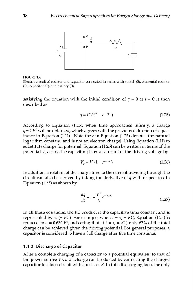
FIGURE 1.6
Electric circuit of resistor and capacitor connected in series with switch (S), elemental resistor
(R), capacitor (C), and battery (B).
satisfying the equation with the initial condition of q = 0 at t = 0 is then
described as
q = CV 0 (1 – e –t/RC )
(1.25)
According to Equation (1.25), when time approaches infinity, a charge
q = CV 0 will be obtained, which agrees with the previous definition of capacitance in Equation (1.11). [Note the e in Equation (1.25) denotes the natural
logarithm constant, and is not an electron charge]. Using Equation (1.11) to
substitute charge for potential, Equation (1.25) can be written in terms of the
potential V p across the capacitor plates as a result of the driving voltage by
V p = V 0 (1 – e –t/RC )
(1.26)
In addition, a relation of the charge time to the current traveling through the
circuit can also be derived by taking the derivative of q with respect to t in
Equation (1.25) as shown by
dq
V
0 −t RC
I
e
= =
/
dt
R
(1.27)
In all these equations, the RC product is the capacitive time constant and is
represented by τ c (= RC). For example, when t = τ c = RC, Equation (1.25) is
reduced to q = 0.63CV 0 , indicating that at t = τ c = RC, only 63% of the total
charge can be achieved given the driving potential. For general purposes, a
capacitor is considered to have a full charge after five time constants.
1.4.3 Discharge of Capacitor
After a complete charging of a capacitor to a potential equivalent to that of
the power source V 0 , a discharge can be started by connecting the charged
capacitor to a loop circuit with a resistor R. In this discharging loop, the only