

-Z
Im , Ω.cm
2
480 KHz
0.0
1.0
2.0
3.0
4.0
5.0
6.0
7.0
8.0
9.0
10.0
0.08 Hz
0.0001 Hz
R esr = 0.3 Ω.cm
2
R P = 5000 Ω.cm
2
R P = 50 Ω.cm
2
R P = 10 Ω.cm
2
R P = 5 Ω.cm
2
C F = 1.0 F.cm
–2
C dl = 0.3 W.cm
–2
R ct = 0.16 W.cm
2
0.0
1.0
2.0
3.0
4.0
5.0
6.0
7.0
8.0
9.0 10.0 11.0
Z R , Ω.cm
2
300
Electrochemical Supercapacitors for Energy Storage and Delivery
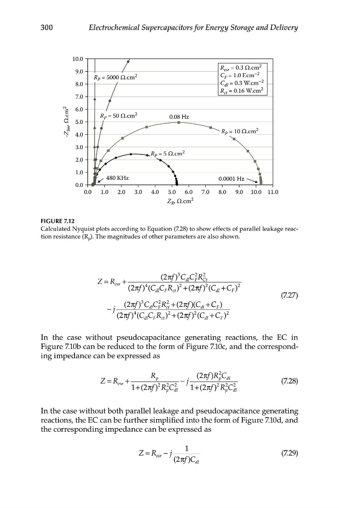
FIGURE 7.12
Calculated Nyquist plots according to Equation (7.28) to show effects of parallel leakage reaction resistance (R p ). The magnitudes of other parameters are also shown.
(2 πf C
)
3
2
dl C F R
2
Z R
=
Ct
esr +
(2πf )
4 (C dl C F R ct )
2
+ (2π πf ) (
2 C
2
dl + C F )
(7.27)
(2πf C
)
3
C
2 R
2
+ (2 πf )(C + C C )
− j
dl F ct
dl
F
(2 πf )
4 (C
2
dl C F R c t ) + ( 2πf )
2 (C + C )
2
dl
F
In the case without pseudocapacitance generating reactions, the EC in
Figure 7.10b can be reduced to the form of Figure 7.10c, and the corresponding impedance can be expressed as
R
( 2πf R
)
2 C
Z R
=
p
esr +
2 2
−
2
j
p dl
(7.28)
1 2
+ ( πf R
) C
2 2 2
p dl
1 2
+ ( πf ) ) R C
p dl
In the case without both parallel leakage and pseudocapacitance generating
reactions, the EC can be further simplified into the form of Figure 7.10d, and
the corresponding impedance can be expressed as
1
Z R
= esr − j
(7.29)
(2πf C
) dl
Im , Ω.cm
2
480 KHz
0.0
1.0
2.0
3.0
4.0
5.0
6.0
7.0
8.0
9.0
10.0
0.08 Hz
0.0001 Hz
R esr = 0.3 Ω.cm
2
R P = 5000 Ω.cm
2
R P = 50 Ω.cm
2
R P = 10 Ω.cm
2
R P = 5 Ω.cm
2
C F = 1.0 F.cm
–2
C dl = 0.3 W.cm
–2
R ct = 0.16 W.cm
2
0.0
1.0
2.0
3.0
4.0
5.0
6.0
7.0
8.0
9.0 10.0 11.0
Z R , Ω.cm
2
300
Electrochemical Supercapacitors for Energy Storage and Delivery
FIGURE 7.12
Calculated Nyquist plots according to Equation (7.28) to show effects of parallel leakage reaction resistance (R p ). The magnitudes of other parameters are also shown.
(2 πf C
)
3
2
dl C F R
2
Z R
=
Ct
esr +
(2πf )
4 (C dl C F R ct )
2
+ (2π πf ) (
2 C
2
dl + C F )
(7.27)
(2πf C
)
3
C
2 R
2
+ (2 πf )(C + C C )
− j
dl F ct
dl
F
(2 πf )
4 (C
2
dl C F R c t ) + ( 2πf )
2 (C + C )
2
dl
F
In the case without pseudocapacitance generating reactions, the EC in
Figure 7.10b can be reduced to the form of Figure 7.10c, and the corresponding impedance can be expressed as
R
( 2πf R
)
2 C
Z R
=
p
esr +
2 2
−
2
j
p dl
(7.28)
1 2
+ ( πf R
) C
2 2 2
p dl
1 2
+ ( πf ) ) R C
p dl
In the case without both parallel leakage and pseudocapacitance generating
reactions, the EC can be further simplified into the form of Figure 7.10d, and
the corresponding impedance can be expressed as
1
Z R
= esr − j
(7.29)
(2πf C
) dl