

C dl
+
R esr
R P
R ct
C F
–
(a)
C dl
R ct
C F
+
R esr
–
(b)
C dl
+
R esr
–
R P
(c)
+
R esr
C dl
–
(d)
297
Characterization and Diagnosis Techniques
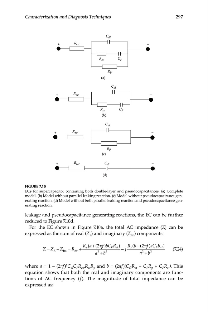
FIGURE 7.10
ECs for supercapacitor containing both double-layer and pseudocapacitances. (a) Complete
model. (b) Model without parallel leaking reaction. (c) Model without pseudocapacitance generating reaction. (d) Model without both parallel leaking reaction and pseudocapacitance generating reaction.
leakage and pseudocapacitance generating reactions, the EC can be further
reduced to Figure 7.10d.
For the EC shown in Figure 7.10a, the total AC impedance (Z) can be
expressed as the sum of real (Z R ) and imaginary (Z Im ) components:
R a
p ( + (2 πf )b C
Z Z
=
+ Z = R
F R
+
c t )
R b
p ( − ( ( 2πf a
) C F c
R t )
R
Im
esr
2
2
− j
2
(7.24)
a + b
a + b
2
where a = 1 – (2πf) 2 C dl C F R esr R ct R p and b = (2πf)(C dl R ct + C F R p + C F R ct ). This
equation shows that both the real and imaginary components are functions of AC frequency ( f). The magnitude of total impedance can be
expressed as:
+
R esr
R P
R ct
C F
–
(a)
C dl
R ct
C F
+
R esr
–
(b)
C dl
+
R esr
–
R P
(c)
+
R esr
C dl
–
(d)
297
Characterization and Diagnosis Techniques
FIGURE 7.10
ECs for supercapacitor containing both double-layer and pseudocapacitances. (a) Complete
model. (b) Model without parallel leaking reaction. (c) Model without pseudocapacitance generating reaction. (d) Model without both parallel leaking reaction and pseudocapacitance generating reaction.
leakage and pseudocapacitance generating reactions, the EC can be further
reduced to Figure 7.10d.
For the EC shown in Figure 7.10a, the total AC impedance (Z) can be
expressed as the sum of real (Z R ) and imaginary (Z Im ) components:
R a
p ( + (2 πf )b C
Z Z
=
+ Z = R
F R
+
c t )
R b
p ( − ( ( 2πf a
) C F c
R t )
R
Im
esr
2
2
− j
2
(7.24)
a + b
a + b
2
where a = 1 – (2πf) 2 C dl C F R esr R ct R p and b = (2πf)(C dl R ct + C F R p + C F R ct ). This
equation shows that both the real and imaginary components are functions of AC frequency ( f). The magnitude of total impedance can be
expressed as: