

287
Characterization and Diagnosis Techniques
using the data from backward potential scanning. Theoretically, the results
from both potential scan directions should be the same. For example, the
specific charge Q in Figure 7.6 in the positive scan direction can be measured to be 154 C.g –1 in a potential range from –0.3 to 1.3 V (E 2 – E 1 = 1.6 V).
Therefore, the specific capacitance (C sp ) of the electrode layer can be calculated to be 96.3 F.g –1 .
7.3.2 Double-Layer Specific Capacitance Characterization
Using Two-Electrode Test Cell
Using a two-electrode cell, CVs can also be recorded by connecting both the
reference and counter electrode probes of the potentiostat to one electrode of
the test cell, while connecting the working electrode to the other electrode
of the cell. In this case, the potential scan should be called the “cell voltage scan” because the voltage change over time is actually the cell voltage
change.
The other difference is that the capacitance obtained using CVs recorded
by the two-electrode test cell involves contributions from both electrodes,
rather than only from one. If the two electrodes are not identical, the better approach is to use the three-electrode cell for measurement to obtain
data about the individual electrodes. In the case of a symmetric cell where
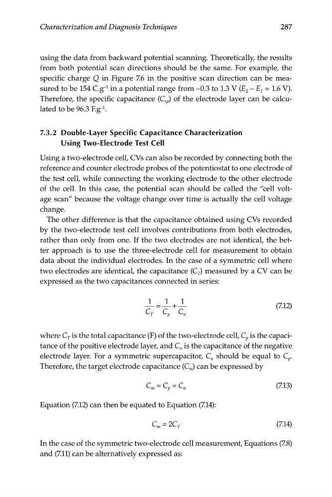
two electrodes are identical, the capacitance (C T ) measured by a CV can be
expressed as the two capacitances connected in series:
1
1
1
=
+
(7.12)
C
C C
T
p
n
where C T is the total capacitance (F) of the two-electrode cell, C p is the capacitance of the positive electrode layer, and C n is the capacitance of the negative
electrode layer. For a symmetric supercapacitor, C n should be equal to C p .
Therefore, the target electrode capacitance (C m ) can be expressed by
C m = C p = C n
(7.13)
Equation (7.12) can then be equated to Equation (7.14):
C m = 2C T
(7.14)
In the case of the symmetric two-electrode cell measurement, Equations (7.8)
and (7.11) can be alternatively expressed as:
Characterization and Diagnosis Techniques
using the data from backward potential scanning. Theoretically, the results
from both potential scan directions should be the same. For example, the
specific charge Q in Figure 7.6 in the positive scan direction can be measured to be 154 C.g –1 in a potential range from –0.3 to 1.3 V (E 2 – E 1 = 1.6 V).
Therefore, the specific capacitance (C sp ) of the electrode layer can be calculated to be 96.3 F.g –1 .
7.3.2 Double-Layer Specific Capacitance Characterization
Using Two-Electrode Test Cell
Using a two-electrode cell, CVs can also be recorded by connecting both the
reference and counter electrode probes of the potentiostat to one electrode of
the test cell, while connecting the working electrode to the other electrode
of the cell. In this case, the potential scan should be called the “cell voltage scan” because the voltage change over time is actually the cell voltage
change.
The other difference is that the capacitance obtained using CVs recorded
by the two-electrode test cell involves contributions from both electrodes,
rather than only from one. If the two electrodes are not identical, the better approach is to use the three-electrode cell for measurement to obtain
data about the individual electrodes. In the case of a symmetric cell where
two electrodes are identical, the capacitance (C T ) measured by a CV can be
expressed as the two capacitances connected in series:
1
1
1
=
+
(7.12)
C
C C
T
p
n
where C T is the total capacitance (F) of the two-electrode cell, C p is the capacitance of the positive electrode layer, and C n is the capacitance of the negative
electrode layer. For a symmetric supercapacitor, C n should be equal to C p .
Therefore, the target electrode capacitance (C m ) can be expressed by
C m = C p = C n
(7.13)
Equation (7.12) can then be equated to Equation (7.14):
C m = 2C T
(7.14)
In the case of the symmetric two-electrode cell measurement, Equations (7.8)
and (7.11) can be alternatively expressed as: