

L
R l
Z P
—
(a)
C
C
2
2
n = 1
n = 2
Z P
—
C
τ
2
τ
2
π 2 n
2 .C
π
2 n
2 .C
(b)
261
Coupling with Batteries and Fuel Cells
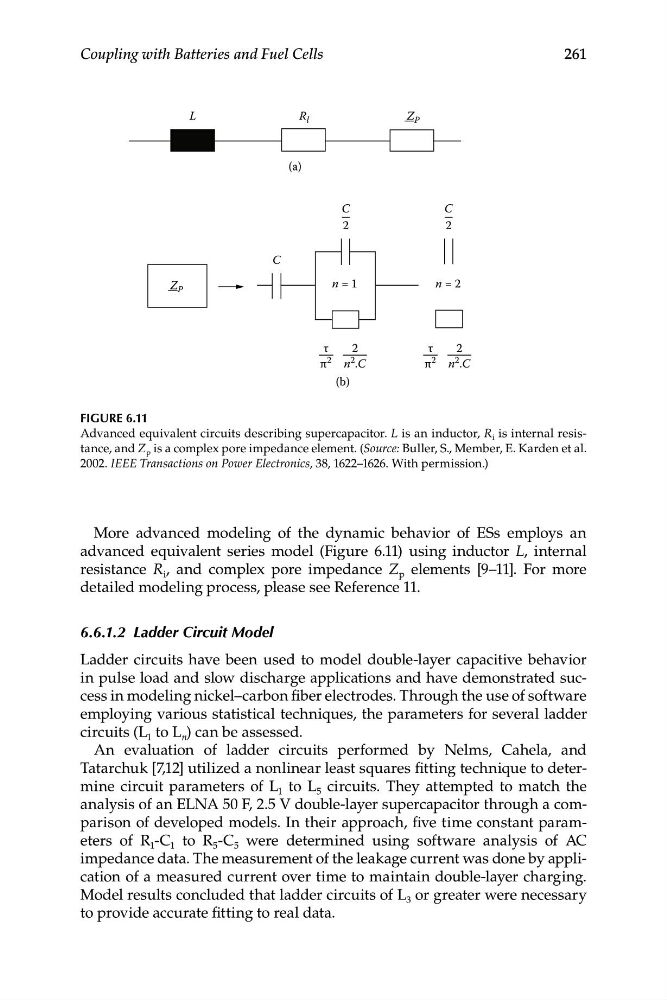
FIGURE 6.11
Advanced equivalent circuits describing supercapacitor. L is an inductor, R i is internal resistance, and Z p is a complex pore impedance element. (Source: Buller, S., Member, E. Karden et al.
2002. IEEE Transactions on Power Electronics, 38, 1622–1626. With permission.)
More advanced modeling of the dynamic behavior of ESs employs an
advanced equivalent series model (Figure 6.11) using inductor L, internal
resistance R i , and complex pore impedance Z p elements [9–11]. For more
detailed modeling process, please see Reference 11.
6.6.1.2 Ladder Circuit Model
Ladder circuits have been used to model double-layer capacitive behavior
in pulse load and slow discharge applications and have demonstrated success in modeling nickel–carbon fiber electrodes. Through the use of software
employing various statistical techniques, the parameters for several ladder
circuits (L 1 to L n ) can be assessed.
An evaluation of ladder circuits performed by Nelms, Cahela, and
Tatarchuk [7,12] utilized a nonlinear least squares fitting technique to determine circuit parameters of L 1 to L 5 circuits. They attempted to match the
analysis of an ELNA 50 F, 2.5 V double-layer supercapacitor through a comparison of developed models. In their approach, five time constant parameters of R 1 -C 1 to R 5 -C 5 were determined using software analysis of AC
impedance data. The measurement of the leakage current was done by application of a measured current over time to maintain double-layer charging.
Model results concluded that ladder circuits of L 3 or greater were necessary
to provide accurate fitting to real data.
R l
Z P
—
(a)
C
C
2
2
n = 1
n = 2
Z P
—
C
τ
2
τ
2
π 2 n
2 .C
π
2 n
2 .C
(b)
261
Coupling with Batteries and Fuel Cells
FIGURE 6.11
Advanced equivalent circuits describing supercapacitor. L is an inductor, R i is internal resistance, and Z p is a complex pore impedance element. (Source: Buller, S., Member, E. Karden et al.
2002. IEEE Transactions on Power Electronics, 38, 1622–1626. With permission.)
More advanced modeling of the dynamic behavior of ESs employs an
advanced equivalent series model (Figure 6.11) using inductor L, internal
resistance R i , and complex pore impedance Z p elements [9–11]. For more
detailed modeling process, please see Reference 11.
6.6.1.2 Ladder Circuit Model
Ladder circuits have been used to model double-layer capacitive behavior
in pulse load and slow discharge applications and have demonstrated success in modeling nickel–carbon fiber electrodes. Through the use of software
employing various statistical techniques, the parameters for several ladder
circuits (L 1 to L n ) can be assessed.
An evaluation of ladder circuits performed by Nelms, Cahela, and
Tatarchuk [7,12] utilized a nonlinear least squares fitting technique to determine circuit parameters of L 1 to L 5 circuits. They attempted to match the
analysis of an ELNA 50 F, 2.5 V double-layer supercapacitor through a comparison of developed models. In their approach, five time constant parameters of R 1 -C 1 to R 5 -C 5 were determined using software analysis of AC
impedance data. The measurement of the leakage current was done by application of a measured current over time to maintain double-layer charging.
Model results concluded that ladder circuits of L 3 or greater were necessary
to provide accurate fitting to real data.