

9
Fundamentals of Electric Capacitors
1.3.1 Dielectric Materials and Constants
As mentioned above, a dielectric is the middle layer between the two conductive plates of a capacitor and is generally composed of an electric insulation material such as a vacuum, non-ionized gas, solid such as a ceramic or
polymer, or a liquid (aqueous or non-aqueous electrolyte). Two electrodes
located at both sides of the dielectric collect the current. Since a dielectric
is the primary material responsible for the storage of charge in capacitor
devices, it exhibits extremely low conduction currents from free electrons
and ion impurities. Although solids and liquids are predominantly used as
insulators, vacuums and non-ionized gases are better insulators.
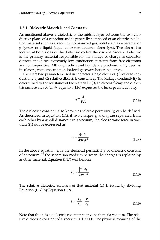
There are two parameters used in characterizing dielectrics: (1) leakage conductivity σ l and (2) relative dielectric constant ε r . The leakage conductivity is
determined by the resistance of the material R (Ω); thickness d (cm); and dielectric surface area A (cm 2 ). Equation (1.16) expresses the leakage conductivity.
d
σ l =
(1.16)
RA
The dielectric constant, also known as relative permittivity, can be defined.
As described in Equation (1.1), if two charges q 1 and q 2 are separated from
each other by a small distance r in a vacuum, the electrostatic force in vacuum (F 0 ) can be expressed as
q q
1 2
F 0 =
4πε 0 r
2
(1.17)
In the above equation, ε 0 is the electrical permittivity or dielectric constant
of a vacuum. If the separation medium between the charges is replaced by
another material, Equation (1.17) will become
q q
1 2
F m =
4πε r
2
(1.18)
The relative dielectric constant of that material (ε r ) is found by dividing
Equation (1.17) by Equation (1.18).
F 0 ε
ε =
=
r
F m ε 0
(1.19)
Note that this ε r is a dielectric constant relative to that of a vacuum. The relative dielectric constant of a vacuum is 1.00000. The physical meaning of the
Fundamentals of Electric Capacitors
1.3.1 Dielectric Materials and Constants
As mentioned above, a dielectric is the middle layer between the two conductive plates of a capacitor and is generally composed of an electric insulation material such as a vacuum, non-ionized gas, solid such as a ceramic or
polymer, or a liquid (aqueous or non-aqueous electrolyte). Two electrodes
located at both sides of the dielectric collect the current. Since a dielectric
is the primary material responsible for the storage of charge in capacitor
devices, it exhibits extremely low conduction currents from free electrons
and ion impurities. Although solids and liquids are predominantly used as
insulators, vacuums and non-ionized gases are better insulators.
There are two parameters used in characterizing dielectrics: (1) leakage conductivity σ l and (2) relative dielectric constant ε r . The leakage conductivity is
determined by the resistance of the material R (Ω); thickness d (cm); and dielectric surface area A (cm 2 ). Equation (1.16) expresses the leakage conductivity.
d
σ l =
(1.16)
RA
The dielectric constant, also known as relative permittivity, can be defined.
As described in Equation (1.1), if two charges q 1 and q 2 are separated from
each other by a small distance r in a vacuum, the electrostatic force in vacuum (F 0 ) can be expressed as
q q
1 2
F 0 =
4πε 0 r
2
(1.17)
In the above equation, ε 0 is the electrical permittivity or dielectric constant
of a vacuum. If the separation medium between the charges is replaced by
another material, Equation (1.17) will become
q q
1 2
F m =
4πε r
2
(1.18)
The relative dielectric constant of that material (ε r ) is found by dividing
Equation (1.17) by Equation (1.18).
F 0 ε
ε =
=
r
F m ε 0
(1.19)
Note that this ε r is a dielectric constant relative to that of a vacuum. The relative dielectric constant of a vacuum is 1.00000. The physical meaning of the