

+ Positive charge
– Negative charge, carried by ion
+
–
V
+
–
–
+
+
+
–
–
+
+
–
–
+
+
–
–
+
+
–
–
+
+
–
–
+
+
–
–
–
+
+
–
+
+
–
–
+
–
+
–
Positive electrode
Separator
Negative electrode
(Conducting material)
(Conducting material)
Electrolyte medium
Electrode Dielectric
A
B
(a)
(b)
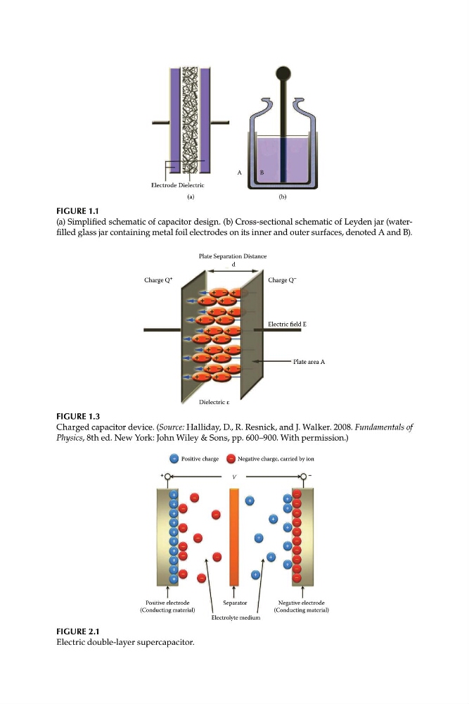
FIGURE 1.1
(a) Simplified schematic of capacitor design. (b) Cross-sectional schematic of Leyden jar (waterfilled glass jar containing metal foil electrodes on its inner and outer surfaces, denoted A and B).
Plate Separation Distance
d
Charge Q +
Charge Q –
Electric field E
Plate area A
Dielectric ε
FIGURE 1.3
Charged capacitor device. (Source: Halliday, D., R. Resnick, and J. Walker. 2008. Fundamentals of
Physics, 8th ed. New York: John Wiley & Sons, pp. 600–900. With permission.)
FIGURE 2.1
Electric double-layer supercapacitor.
– Negative charge, carried by ion
+
–
V
+
–
–
+
+
+
–
–
+
+
–
–
+
+
–
–
+
+
–
–
+
+
–
–
+
+
–
–
–
+
+
–
+
+
–
–
+
–
+
–
Positive electrode
Separator
Negative electrode
(Conducting material)
(Conducting material)
Electrolyte medium
Electrode Dielectric
A
B
(a)
(b)
FIGURE 1.1
(a) Simplified schematic of capacitor design. (b) Cross-sectional schematic of Leyden jar (waterfilled glass jar containing metal foil electrodes on its inner and outer surfaces, denoted A and B).
Plate Separation Distance
d
Charge Q +
Charge Q –
Electric field E
Plate area A
Dielectric ε
FIGURE 1.3
Charged capacitor device. (Source: Halliday, D., R. Resnick, and J. Walker. 2008. Fundamentals of
Physics, 8th ed. New York: John Wiley & Sons, pp. 600–900. With permission.)
FIGURE 2.1
Electric double-layer supercapacitor.