

Melting Point
Viscosity
Dielectric Constant
Solvent
(°C)
(Pa∙s –1 )
(ε)
Acetonitrile
−43.8
0.369
36.64
γ-Butyrolactone
−43.3
1.72
39
Dimethyl ketone
−94.8
0.306
21.01
Propylene carbonate
−48.8
2.513
66.14
Water
Density
Conductivity
Electrolyte Solution
(g/cm 3 )
(mS/cm)
ΔU
Aqueous, KOH
1.29
540
1
Aqueous, KCl
1.09
210
1
Aqueous, sulfuric acid
1.2
750
1
Aqueous, sodium sulfate
1.13
91.1
1
Aqueous, potassium sulfate
1.08
88.6
1
Propylene carbonate, Et 4 NBF 4
1.2
14.5
2.5 to 3
Acetonitrile, Et 4 NBF 4
0.78
59.9
2.5 to 3
IL, Et 2 MeIm + BF 4.
1.3 to 1.5
8 (25°C)
4
IL, Et 2 MeIm + BF 4.
14 (100°C)
3.25
181
Components and Materials for Electrochemical Supercapacitors
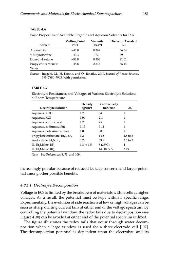
TABLE 4.6
Basic Properties of Available Organic and Aqueous Solvents for ESs
Source: Inagaki, M., H. Konno, and O. Tanaike. 2010. Journal of Power Sources,
195, 7880–7903. With permission.
TABLE 4.7
Electrolyte Resistances and Voltages of Various Electrolyte Solutions
at Room Temperature
Note: See References 8, 73, and 109.
increasingly popular because of reduced leakage concerns and larger potential among other possible benefits.
4.3.1.1 Electrolyte Decomposition
Voltage in ECs is limited by the breakdown of materials within cells at higher
voltages. As a result, the potential must be kept within a specific range.
Experimentally, the evolution of side reactions at low or high voltages can be
seen as sharp drifting current tails at either end of the voltage spectrum. By
controlling the potential window, the redox tails due to decomposition (see
Figure 4.30) can be avoided at either end of the potential spectrum utilized.
The figure illustrates the redox tails that occur through water decomposition when a large window is used for a three-electrode cell [107].
The decomposition potential is dependent upon the electrolyte and its
Viscosity
Dielectric Constant
Solvent
(°C)
(Pa∙s –1 )
(ε)
Acetonitrile
−43.8
0.369
36.64
γ-Butyrolactone
−43.3
1.72
39
Dimethyl ketone
−94.8
0.306
21.01
Propylene carbonate
−48.8
2.513
66.14
Water
Density
Conductivity
Electrolyte Solution
(g/cm 3 )
(mS/cm)
ΔU
Aqueous, KOH
1.29
540
1
Aqueous, KCl
1.09
210
1
Aqueous, sulfuric acid
1.2
750
1
Aqueous, sodium sulfate
1.13
91.1
1
Aqueous, potassium sulfate
1.08
88.6
1
Propylene carbonate, Et 4 NBF 4
1.2
14.5
2.5 to 3
Acetonitrile, Et 4 NBF 4
0.78
59.9
2.5 to 3
IL, Et 2 MeIm + BF 4.
1.3 to 1.5
8 (25°C)
4
IL, Et 2 MeIm + BF 4.
14 (100°C)
3.25
181
Components and Materials for Electrochemical Supercapacitors
TABLE 4.6
Basic Properties of Available Organic and Aqueous Solvents for ESs
Source: Inagaki, M., H. Konno, and O. Tanaike. 2010. Journal of Power Sources,
195, 7880–7903. With permission.
TABLE 4.7
Electrolyte Resistances and Voltages of Various Electrolyte Solutions
at Room Temperature
Note: See References 8, 73, and 109.
increasingly popular because of reduced leakage concerns and larger potential among other possible benefits.
4.3.1.1 Electrolyte Decomposition
Voltage in ECs is limited by the breakdown of materials within cells at higher
voltages. As a result, the potential must be kept within a specific range.
Experimentally, the evolution of side reactions at low or high voltages can be
seen as sharp drifting current tails at either end of the voltage spectrum. By
controlling the potential window, the redox tails due to decomposition (see
Figure 4.30) can be avoided at either end of the potential spectrum utilized.
The figure illustrates the redox tails that occur through water decomposition when a large window is used for a three-electrode cell [107].
The decomposition potential is dependent upon the electrolyte and its