

(a)
0.0006
0.003
Current (A)
0.0000
0.2 V/s
0.1 V/s
Current (A)
0.000
0.2 V/s
0.1 V/s
0.05 V/s
0.05 V/s
0.02 V/s
–0.003
0.02 V/s
–0.0006
0.01 V/s
0.01 V/s
–0.4 –0.2
0.0
0.2
0.4
0.6
–0.4 –0.2
0.0
0.2
0.4
0.6
Potential (V)
Potential (V)
(b)
(c)
177
Components and Materials for Electrochemical Supercapacitors
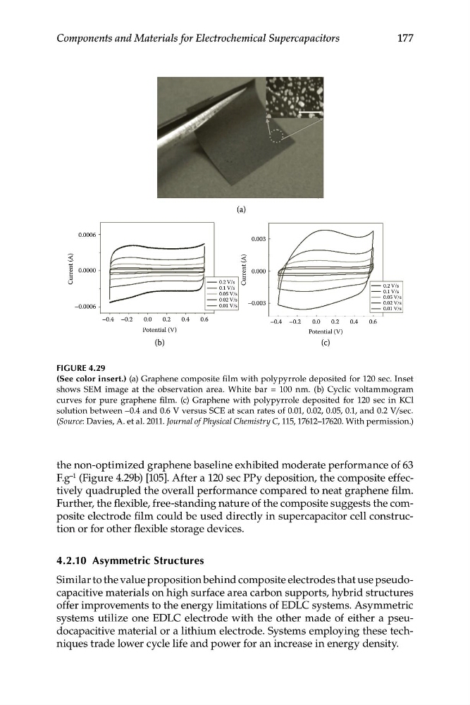
FIGURE 4.29
(See color insert.) (a) Graphene composite film with polypyrrole deposited for 120 sec. Inset
shows SEM image at the observation area. White bar = 100 nm. (b) Cyclic voltammogram
curves for pure graphene film. (c) Graphene with polypyrrole deposited for 120 sec in KCl
solution between –0.4 and 0.6 V versus SCE at scan rates of 0.01, 0.02, 0.05, 0.1, and 0.2 V/sec.
(Source: Davies, A. et al. 2011. Journal of Physical Chemistry C, 115, 17612–17620. With permission.)
the non-optimized graphene baseline exhibited moderate performance of 63
F.g –1 (Figure 4.29b) [105]. After a 120 sec PPy deposition, the composite effectively quadrupled the overall performance compared to neat graphene film.
Further, the flexible, free-standing nature of the composite suggests the composite electrode film could be used directly in supercapacitor cell construction or for other flexible storage devices.
4.2.10 Asymmetric Structures
Similar to the value proposition behind composite electrodes that use pseudocapacitive materials on high surface area carbon supports, hybrid structures
offer improvements to the energy limitations of EDLC systems. Asymmetric
systems utilize one EDLC electrode with the other made of either a pseudocapacitive material or a lithium electrode. Systems employing these techniques trade lower cycle life and power for an increase in energy density.
0.0006
0.003
Current (A)
0.0000
0.2 V/s
0.1 V/s
Current (A)
0.000
0.2 V/s
0.1 V/s
0.05 V/s
0.05 V/s
0.02 V/s
–0.003
0.02 V/s
–0.0006
0.01 V/s
0.01 V/s
–0.4 –0.2
0.0
0.2
0.4
0.6
–0.4 –0.2
0.0
0.2
0.4
0.6
Potential (V)
Potential (V)
(b)
(c)
177
Components and Materials for Electrochemical Supercapacitors
FIGURE 4.29
(See color insert.) (a) Graphene composite film with polypyrrole deposited for 120 sec. Inset
shows SEM image at the observation area. White bar = 100 nm. (b) Cyclic voltammogram
curves for pure graphene film. (c) Graphene with polypyrrole deposited for 120 sec in KCl
solution between –0.4 and 0.6 V versus SCE at scan rates of 0.01, 0.02, 0.05, 0.1, and 0.2 V/sec.
(Source: Davies, A. et al. 2011. Journal of Physical Chemistry C, 115, 17612–17620. With permission.)
the non-optimized graphene baseline exhibited moderate performance of 63
F.g –1 (Figure 4.29b) [105]. After a 120 sec PPy deposition, the composite effectively quadrupled the overall performance compared to neat graphene film.
Further, the flexible, free-standing nature of the composite suggests the composite electrode film could be used directly in supercapacitor cell construction or for other flexible storage devices.
4.2.10 Asymmetric Structures
Similar to the value proposition behind composite electrodes that use pseudocapacitive materials on high surface area carbon supports, hybrid structures
offer improvements to the energy limitations of EDLC systems. Asymmetric
systems utilize one EDLC electrode with the other made of either a pseudocapacitive material or a lithium electrode. Systems employing these techniques trade lower cycle life and power for an increase in energy density.