

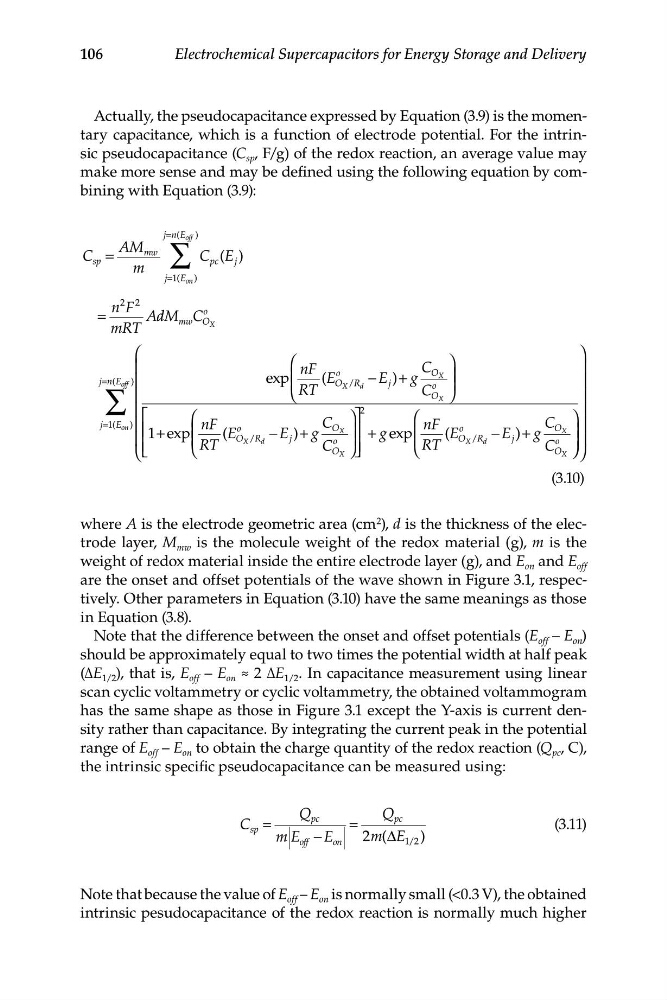
j n
=
AM
C
mw
sp =
m
j =
∑
(E off )
C E
pc ( )
j
1 (E on )
n F
2 2
=
AdM d
o
mRT
mw C O X
⎛
⎞
⎜
⎛
⎞
nF
C
⎟
j n
= ( E off ) ⎜
exp
⎜
(E
o
O /R −
E
j )
+
O
⎟
∑
X
g
X ⎟
⎜
⎟
⎟
⎝ RT
d
C
o
⎜
O X ⎠
⎟
⎜
⎟
j 1(E
⎡
⎛
⎤
2
on )
⎞
=
⎛
⎞
⎜
nF
nF
⎢ ⎢ 1 e
+
⎜
(
o
C
xp
E
− E )+ g
O X ⎟⎥
+ g exp ⎜
(E
o
C
−
O ⎟
⎜
⎢
O X R
⎟
d
⎟
X
/
E )+ g
⎜
j
o
⎜
⎥
RT
⎝
⎠⎦
RT
O
⎝
C
/R
j
⎟
O X
⎝
C
o
⎣
X
d
⎟
O X ⎠ ⎠ ⎠
(3.10)
106
Electrochemical Supercapacitors for Energy Storage and Delivery
Actually, the pseudocapacitance expressed by Equation (3.9) is the momentary capacitance, which is a function of electrode potential. For the intrinsic pseudocapacitance (C sp , F/g) of the redox reaction, an average value may
make more sense and may be defined using the following equation by combining with Equation (3.9):
where A is the electrode geometric area (cm 2 ), d is the thickness of the electrode layer, M mw is the molecule weight of the redox material (g), m is the
weight of redox material inside the entire electrode layer (g), and E on and E off
are the onset and offset potentials of the wave shown in Figure 3.1, respectively. Other parameters in Equation (3.10) have the same meanings as those
in Equation (3.8).
Note that the difference between the onset and offset potentials (E off – E on )
should be approximately equal to two times the potential width at half peak
(ΔE 1/2 ), that is, E off – E on ≈ 2 ΔE 1/2 . In capacitance measurement using linear
scan cyclic voltammetry or cyclic voltammetry, the obtained voltammogram
has the same shape as those in Figure 3.1 except the Y-axis is current density rather than capacitance. By integrating the current peak in the potential
range of E off – E on to obtain the charge quantity of the redox reaction (Q pc , C),
the intrinsic specific pseudocapacitance can be measured using:
Q
Q
C =
pc
=
pc
sp
(3.11)
m E off −
E on 2m E
( Δ 1 2
/ )
Note that because the value of E off – E on is normally small (<0.3 V), the obtained
intrinsic pesudocapacitance of the redox reaction is normally much higher
=
AM
C
mw
sp =
m
j =
∑
(E off )
C E
pc ( )
j
1 (E on )
n F
2 2
=
AdM d
o
mRT
mw C O X
⎛
⎞
⎜
⎛
⎞
nF
C
⎟
j n
= ( E off ) ⎜
exp
⎜
(E
o
O /R −
E
j )
+
O
⎟
∑
X
g
X ⎟
⎜
⎟
⎟
⎝ RT
d
C
o
⎜
O X ⎠
⎟
⎜
⎟
j 1(E
⎡
⎛
⎤
2
on )
⎞
=
⎛
⎞
⎜
nF
nF
⎢ ⎢ 1 e
+
⎜
(
o
C
xp
E
− E )+ g
O X ⎟⎥
+ g exp ⎜
(E
o
C
−
O ⎟
⎜
⎢
O X R
⎟
d
⎟
X
/
E )+ g
⎜
j
o
⎜
⎥
RT
⎝
⎠⎦
RT
O
⎝
C
/R
j
⎟
O X
⎝
C
o
⎣
X
d
⎟
O X ⎠ ⎠ ⎠
(3.10)
106
Electrochemical Supercapacitors for Energy Storage and Delivery
Actually, the pseudocapacitance expressed by Equation (3.9) is the momentary capacitance, which is a function of electrode potential. For the intrinsic pseudocapacitance (C sp , F/g) of the redox reaction, an average value may
make more sense and may be defined using the following equation by combining with Equation (3.9):
where A is the electrode geometric area (cm 2 ), d is the thickness of the electrode layer, M mw is the molecule weight of the redox material (g), m is the
weight of redox material inside the entire electrode layer (g), and E on and E off
are the onset and offset potentials of the wave shown in Figure 3.1, respectively. Other parameters in Equation (3.10) have the same meanings as those
in Equation (3.8).
Note that the difference between the onset and offset potentials (E off – E on )
should be approximately equal to two times the potential width at half peak
(ΔE 1/2 ), that is, E off – E on ≈ 2 ΔE 1/2 . In capacitance measurement using linear
scan cyclic voltammetry or cyclic voltammetry, the obtained voltammogram
has the same shape as those in Figure 3.1 except the Y-axis is current density rather than capacitance. By integrating the current peak in the potential
range of E off – E on to obtain the charge quantity of the redox reaction (Q pc , C),
the intrinsic specific pseudocapacitance can be measured using:
Q
Q
C =
pc
=
pc
sp
(3.11)
m E off −
E on 2m E
( Δ 1 2
/ )
Note that because the value of E off – E on is normally small (<0.3 V), the obtained
intrinsic pesudocapacitance of the redox reaction is normally much higher