

82
Electrochemical Supercapacitors for Energy Storage and Delivery
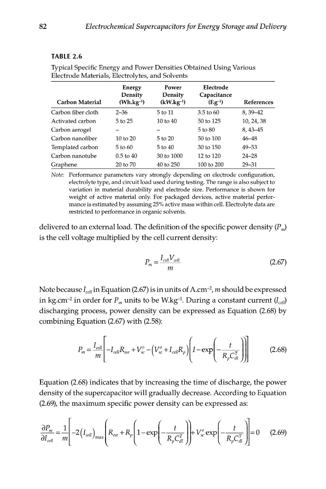
TABLE 2.6
Typical Specific Energy and Power Densities Obtained Using Various
Electrode Materials, Electrolytes, and Solvents
Carbon Material
Energy
Density
(Wh.kg –1 )
Power
Density
(kW.kg –1 )
Electrode
Capacitance
(F.g –1 )
References
Carbon fiber cloth
2–36
5 to 11
3.5 to 60
8, 39–42
Activated carbon
5 to 25
10 to 40
50 to 125
10, 24, 38
Carbon aerogel
–
–
5 to 80
8, 43–45
Carbon nanofiber
10 to 20
5 to 20
50 to 100
46–48
Templated carbon
5 to 60
5 to 40
30 to 150
49–53
Carbon nanotube
0.5 to 40
30 to 1000
12 to 120
24–28
Graphene
20 to 70
40 to 250
100 to 200
29–31
Note: Performance parameters vary strongly depending on electrode configuration,
electrolyte type, and circuit load used during testing. The range is also subject to
variation in material durability and electrode size. Performance is shown for
weight of active material only. For packaged devices, active material performance is estimated by assuming 25% active mass within cell. Electrolyte data are
restricted to performance in organic solvents.
delivered to an external load. The definition of the specific power density (P m )
is the cell voltage multiplied by the cell current density:
I cell V
P
cell
m =
(2.67)
m
Note because I cell in Equation (2.67) is in units of A.cm –2 , m should be expressed
in kg.cm –2 in order for P m units to be W.kg –1 . During a constant current (I cell )
discharging process, power density can be expressed as Equation (2.68) by
combining Equation (2.67) with (2.58):
⎡
⎛
⎛
⎞ ⎞⎤
I
P =
cell ⎢
t
−I R + V
o
m
cell esr
sc − V
o
+ I R ⎜ I − exp p ⎜ −
⎟ ⎟⎥
(2.68)
m ⎢
( sc cell p ) ⎜
⎜
T ⎟
⎣
⎝
⎝ R C ⎟
p dl
⎥
⎠ ⎠ ⎦
Equation (2.68) indicates that by increasing the time of discharge, the power
density of the supercapacitor will gradually decrease. According to Equation
(2.69), the maximum specific power density can be expressed as:
⎡
⎛
⎛
⎛
⎞ ⎞
⎛
⎞ ⎤
∂P m 1 ⎢
t
o
t ⎥
=
−2 I
⎜ R + R
∂I
m ⎢ ( cell ) ⎜
esr
p
⎜ 1− exp ⎜ −
⎟ ⎟
T
V
⎜
⎜
⎟
R C
T
+
⎟
sc exp ⎜ −
⎟ = 0 (2.69)
max
⎜
⎟
cell
⎥
⎣
⎝ ⎝
⎝
⎝
⎠
T
p dl ⎠
⎝ R C
p dl ⎠ ⎦
Electrochemical Supercapacitors for Energy Storage and Delivery
TABLE 2.6
Typical Specific Energy and Power Densities Obtained Using Various
Electrode Materials, Electrolytes, and Solvents
Carbon Material
Energy
Density
(Wh.kg –1 )
Power
Density
(kW.kg –1 )
Electrode
Capacitance
(F.g –1 )
References
Carbon fiber cloth
2–36
5 to 11
3.5 to 60
8, 39–42
Activated carbon
5 to 25
10 to 40
50 to 125
10, 24, 38
Carbon aerogel
–
–
5 to 80
8, 43–45
Carbon nanofiber
10 to 20
5 to 20
50 to 100
46–48
Templated carbon
5 to 60
5 to 40
30 to 150
49–53
Carbon nanotube
0.5 to 40
30 to 1000
12 to 120
24–28
Graphene
20 to 70
40 to 250
100 to 200
29–31
Note: Performance parameters vary strongly depending on electrode configuration,
electrolyte type, and circuit load used during testing. The range is also subject to
variation in material durability and electrode size. Performance is shown for
weight of active material only. For packaged devices, active material performance is estimated by assuming 25% active mass within cell. Electrolyte data are
restricted to performance in organic solvents.
delivered to an external load. The definition of the specific power density (P m )
is the cell voltage multiplied by the cell current density:
I cell V
P
cell
m =
(2.67)
m
Note because I cell in Equation (2.67) is in units of A.cm –2 , m should be expressed
in kg.cm –2 in order for P m units to be W.kg –1 . During a constant current (I cell )
discharging process, power density can be expressed as Equation (2.68) by
combining Equation (2.67) with (2.58):
⎡
⎛
⎛
⎞ ⎞⎤
I
P =
cell ⎢
t
−I R + V
o
m
cell esr
sc − V
o
+ I R ⎜ I − exp p ⎜ −
⎟ ⎟⎥
(2.68)
m ⎢
( sc cell p ) ⎜
⎜
T ⎟
⎣
⎝
⎝ R C ⎟
p dl
⎥
⎠ ⎠ ⎦
Equation (2.68) indicates that by increasing the time of discharge, the power
density of the supercapacitor will gradually decrease. According to Equation
(2.69), the maximum specific power density can be expressed as:
⎡
⎛
⎛
⎛
⎞ ⎞
⎛
⎞ ⎤
∂P m 1 ⎢
t
o
t ⎥
=
−2 I
⎜ R + R
∂I
m ⎢ ( cell ) ⎜
esr
p
⎜ 1− exp ⎜ −
⎟ ⎟
T
V
⎜
⎜
⎟
R C
T
+
⎟
sc exp ⎜ −
⎟ = 0 (2.69)
max
⎜
⎟
cell
⎥
⎣
⎝ ⎝
⎝
⎝
⎠
T
p dl ⎠
⎝ R C
p dl ⎠ ⎦