

146
7 III-Nitride LED Quantum Efficiency Improvement Technology
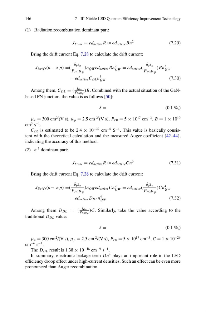
(1) Radiation recombination dominant part:
J T otal = ed active R ≈ ed active Bn
2
(7.29)
Bring the drift current Eq. 7.28 to calculate the drift current:
J Dri f t (n− > p) =(
δμ n
P P0 μ p
)n QW ed active Bn
2
QW = ed active (
δμ n
P P0 μ p
)Bn
3
QW
= ed active C DL n
3
QW
(7.30)
Among them, C DL = (
δμ n
P P0 μ p
)B. Combined with the actual situation of the GaNbased PN junction, the value is as follows [50]:
δ =
(0.1 %,)
μ n = 300 cm
2/ (V s), μ p = 2.5 cm
2/ (V s), P P0 = 5 × 10
17 cm
−3 , B = 1 × 10
10
cm
3 s
−1 .
C DL is estimated to be 2.4 × 10
−29 cm
−6 S
−1 . This value is basically consistent with the theoretical calculation and the measured Auger coefficient [42–44],
indicating the accuracy of this method.
(2) n
3 dominant part:
J T otal = ed active R ≈ ed active Cn
3
(7.31)
Bring the drift current Eq. 7.28 to calculate the drift current:
J Dri f t (n− > p) =(
δμ n
P P0 μ p
)n QW ed active Cn
2
QW = ed active (
δμ n
P P0 μ p
)Cn
4
QW
= ed active D DL n
4
QW
(7.32)
Among them D DL = (
δμ n
P P0 μ p
)C. Similarly, take the value according to the
traditional D DL value:
δ =
(0.1 %,)
μ n = 300 cm
2 /(V s), μ p = 2.5 cm
2 /(V s), P P0 = 5 × 10
17 cm
−3 , C = 1 × 10
−29
cm
−6 s
−1 .
The D DL result is 1.38 × 10
−48 cm
−9 s
−1 .
In summary, electronic leakage term Dn
4 plays an important role in the LED
efficiency droop effect under high-current densities. Such an effect can be even more
pronounced than Auger recombination.
7 III-Nitride LED Quantum Efficiency Improvement Technology
(1) Radiation recombination dominant part:
J T otal = ed active R ≈ ed active Bn
2
(7.29)
Bring the drift current Eq. 7.28 to calculate the drift current:
J Dri f t (n− > p) =(
δμ n
P P0 μ p
)n QW ed active Bn
2
QW = ed active (
δμ n
P P0 μ p
)Bn
3
QW
= ed active C DL n
3
QW
(7.30)
Among them, C DL = (
δμ n
P P0 μ p
)B. Combined with the actual situation of the GaNbased PN junction, the value is as follows [50]:
δ =
(0.1 %,)
μ n = 300 cm
2/ (V s), μ p = 2.5 cm
2/ (V s), P P0 = 5 × 10
17 cm
−3 , B = 1 × 10
10
cm
3 s
−1 .
C DL is estimated to be 2.4 × 10
−29 cm
−6 S
−1 . This value is basically consistent with the theoretical calculation and the measured Auger coefficient [42–44],
indicating the accuracy of this method.
(2) n
3 dominant part:
J T otal = ed active R ≈ ed active Cn
3
(7.31)
Bring the drift current Eq. 7.28 to calculate the drift current:
J Dri f t (n− > p) =(
δμ n
P P0 μ p
)n QW ed active Cn
2
QW = ed active (
δμ n
P P0 μ p
)Cn
4
QW
= ed active D DL n
4
QW
(7.32)
Among them D DL = (
δμ n
P P0 μ p
)C. Similarly, take the value according to the
traditional D DL value:
δ =
(0.1 %,)
μ n = 300 cm
2 /(V s), μ p = 2.5 cm
2 /(V s), P P0 = 5 × 10
17 cm
−3 , C = 1 × 10
−29
cm
−6 s
−1 .
The D DL result is 1.38 × 10
−48 cm
−9 s
−1 .
In summary, electronic leakage term Dn
4 plays an important role in the LED
efficiency droop effect under high-current densities. Such an effect can be even more
pronounced than Auger recombination.