

Course notes
51
ORJȦ
<
,P=
ò5H=
Ȧ
Ȧ
²²
Ȧ
Ȧ
Ȧ
Ȧ
5H=
<
,P=
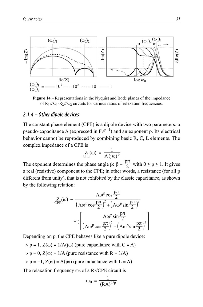
Figure 14 – Representations in the Nyquist and Bode planes of the impedance
of R 1 // C 1 -R 2 // C 2 circuits for various ratios of relaxation frequencies.
2.1.4 – Other dipole devices
The constant phase element (CPE) is a dipole device with two parameters: a
pseudo-capacitance A (expressed in F s
p−1
) and an exponent p. Its electrical
behavior cannot be reproduced by combining basic R, C, L elements. The
complex impedance of a CPE is
( )
( )
1
Z
A j
CPE
p
ω
ω
=
The exponent determines the phase angle β:
2
p
β
π
=
with 0 ≤ p ≤ 1. It gives
a real (resistive) component to the CPE; in other words, a resistance (for all p
different from unity), that is not exhibited by the classic capacitance, as shown
by the following relation:
( )
Z
A cos 2
p
A sin 2
p
A cos 2
p
j
A cos 2
p
A sin 2
p
A sin 2
p
CPE
p
2
p
2
p
p
2
p
2
p
ω
ω
π
ω
π
ω
π
ω
π
ω
π
ω
π
=
+
−
+
`
`
`
`
j
j
j
j
>
H
Depending on p, the CPE behaves like a pure dipole device:
2 p = 1, Z(ω) = 1/A(jω) (pure capacitance with C = A)
2 p = 0, Z(ω) = 1/A (pure resistance with R = 1/A)
2 p = −1, Z(ω) = A(jω) (pure inductance with L = A)
The relaxation frequency ω 0 of a R //CPE circuit is
( )
1
RA
/
0
1 p
ω =
51
ORJȦ
<
,P=
ò5H=
Ȧ
Ȧ
²²
Ȧ
Ȧ
Ȧ
Ȧ
5H=
<
,P=
Figure 14 – Representations in the Nyquist and Bode planes of the impedance
of R 1 // C 1 -R 2 // C 2 circuits for various ratios of relaxation frequencies.
2.1.4 – Other dipole devices
The constant phase element (CPE) is a dipole device with two parameters: a
pseudo-capacitance A (expressed in F s
p−1
) and an exponent p. Its electrical
behavior cannot be reproduced by combining basic R, C, L elements. The
complex impedance of a CPE is
( )
( )
1
Z
A j
CPE
p
ω
ω
=
The exponent determines the phase angle β:
2
p
β
π
=
with 0 ≤ p ≤ 1. It gives
a real (resistive) component to the CPE; in other words, a resistance (for all p
different from unity), that is not exhibited by the classic capacitance, as shown
by the following relation:
( )
Z
A cos 2
p
A sin 2
p
A cos 2
p
j
A cos 2
p
A sin 2
p
A sin 2
p
CPE
p
2
p
2
p
p
2
p
2
p
ω
ω
π
ω
π
ω
π
ω
π
ω
π
ω
π
=
+
−
+
`
`
`
`
j
j
j
j
>
H
Depending on p, the CPE behaves like a pure dipole device:
2 p = 1, Z(ω) = 1/A(jω) (pure capacitance with C = A)
2 p = 0, Z(ω) = 1/A (pure resistance with R = 1/A)
2 p = −1, Z(ω) = A(jω) (pure inductance with L = A)
The relaxation frequency ω 0 of a R //CPE circuit is
( )
1
RA
/
0
1 p
ω =