

Exercises
123
2. In the setup used, the gold serves as an inert probe; that is, a purely electric
(as opposed to electrochemical) probe. Write the equilibrium involving the
electrons present in the gold and in the non-stoichiometric compound.
3. The use of a stabilized zirconia micro-point allows us to consider in a first
approximation that no flux crosses the interface MO 1−x / YSZ. Given these
conditions, write the expression relating the electrochemical potentials of
the species O
2−
in MO 1−x and in YSZ.
4. Assuming that the MO 1−x surface is an equipotential, draw a qualitative
graph of the potential across the chain.
5. What type of conductivity can we determine based on measurements of a
semipermeability flux?
6. Establish the expression for the emf ΔE of the cell as a function of P * O 2
and P O 2 .
Exercise 3.17 – Determination of electronic conductivity
by electrochemical semipermeability
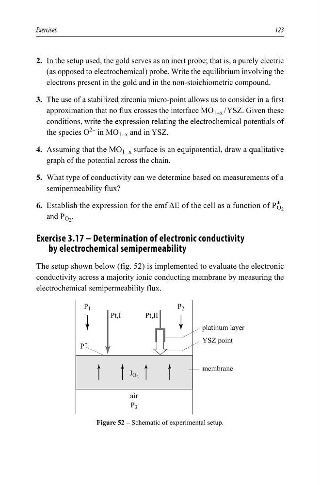
The setup shown below (fig. 52) is implemented to evaluate the electronic
conductivity across a majority ionic conducting membrane by measuring the
electrochemical semipermeability flux.
SODWLQXPOD\HU
<6=SRLQW
PHPEUDQH
3W,,
3W,
DLU
3
- 2
3
3
3
Figure 52 – Schematic of experimental setup.
123
2. In the setup used, the gold serves as an inert probe; that is, a purely electric
(as opposed to electrochemical) probe. Write the equilibrium involving the
electrons present in the gold and in the non-stoichiometric compound.
3. The use of a stabilized zirconia micro-point allows us to consider in a first
approximation that no flux crosses the interface MO 1−x / YSZ. Given these
conditions, write the expression relating the electrochemical potentials of
the species O
2−
in MO 1−x and in YSZ.
4. Assuming that the MO 1−x surface is an equipotential, draw a qualitative
graph of the potential across the chain.
5. What type of conductivity can we determine based on measurements of a
semipermeability flux?
6. Establish the expression for the emf ΔE of the cell as a function of P * O 2
and P O 2 .
Exercise 3.17 – Determination of electronic conductivity
by electrochemical semipermeability
The setup shown below (fig. 52) is implemented to evaluate the electronic
conductivity across a majority ionic conducting membrane by measuring the
electrochemical semipermeability flux.
SODWLQXPOD\HU
<6=SRLQW
PHPEUDQH
3W,,
3W,
DLU
3
- 2
3
3
3
Figure 52 – Schematic of experimental setup.