

5 Suppression of Internal Conversions from Pseudo-Degenerate …
87
a
c
Dimer Model
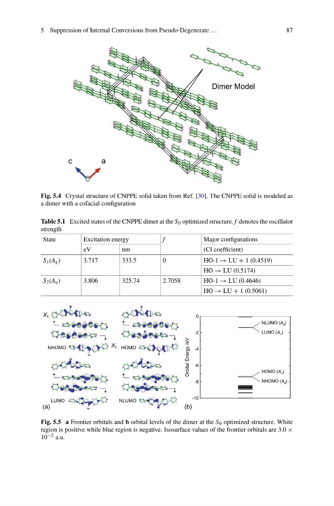
Fig. 5.4 Crystal structure of CNPPE solid taken from Ref. [30]. The CNPPE solid is modeled as
a dimer with a cofacial configuration
Table 5.1 Excited states of the CNPPE dimer at the S 0 optimized structure. f denotes the oscillator
strength
State
Excitation energy
f
Major configurations
eV
nm
(CI coefficient)
S 1 (A g )
3.717
333.5
0
HO-1 → LU + 1 (0.4519)
HO → LU (0.5174)
S 2 (A u )
3.806
325.74
2.7058
HO-1 → LU (0.4646)
HO → LU + 1 (0.5061)
NHOMO
HOMO
LUMO
NLUMO
-10
-8
-6
-4
-2
0
Orbital Energy /eV
HOMO (A u )
NHOMO (A g )
NLUMO (A g )
LUMO (A u )
(a)
(b)
X 1
X 2
Fig. 5.5 a Frontier orbitals and b orbital levels of the dimer at the S 0 optimized structure. White
region is positive while blue region is negative. Isosurface values of the frontier orbitals are 3.0 ×
10 −2 a.u.
87
a
c
Dimer Model
Fig. 5.4 Crystal structure of CNPPE solid taken from Ref. [30]. The CNPPE solid is modeled as
a dimer with a cofacial configuration
Table 5.1 Excited states of the CNPPE dimer at the S 0 optimized structure. f denotes the oscillator
strength
State
Excitation energy
f
Major configurations
eV
nm
(CI coefficient)
S 1 (A g )
3.717
333.5
0
HO-1 → LU + 1 (0.4519)
HO → LU (0.5174)
S 2 (A u )
3.806
325.74
2.7058
HO-1 → LU (0.4646)
HO → LU + 1 (0.5061)
NHOMO
HOMO
LUMO
NLUMO
-10
-8
-6
-4
-2
0
Orbital Energy /eV
HOMO (A u )
NHOMO (A g )
NLUMO (A g )
LUMO (A u )
(a)
(b)
X 1
X 2
Fig. 5.5 a Frontier orbitals and b orbital levels of the dimer at the S 0 optimized structure. White
region is positive while blue region is negative. Isosurface values of the frontier orbitals are 3.0 ×
10 −2 a.u.