

142
7 Numerical Analysis of Macro-fiber Composite Structures
0
100
200
300
0
50
0
0.5
1
Θ
1 (mm)
Θ
2 (mm)
Θ
3
(mm)
(a) MFC-d33 with fiber angle of 0
◦
0
100
200
300
0
50
0
0.5
1
Θ
1 (mm)
Θ
2 (mm)
Θ
3
(mm)
(b) MFC-d33 with fiber angle of 30
◦
0
100
200
300
0
50
0
0.5
1
Θ
1 (mm)
Θ
2 (mm)
Θ
3
(mm)
(c) MFC-d33 with fiber angle of 45
◦
0
100
200
300
0
50
−0.2
0
0.2
0.4
0.6
Θ
1 (mm)
Θ
2 (mm)
Θ
3
(mm)
(d) MFC-d33 with fiber angle of 60
◦
0
100
200
300
0
50
−0.5
0
0.5
Θ
1 (mm)
Θ
2 (mm)
Θ
3
(mm)
(e) MFC-d33 with fiber angle of 75
◦
0
100
200
300
0
50
−0.5
0
0.5
Θ
1 (mm)
Θ
2 (mm)
Θ
3
(mm)
(f) MFC-d33 with fiber angle of 90
◦
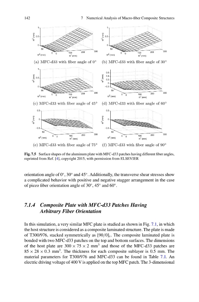
Fig. 7.5 Surface shapes of the aluminum plate with MFC-d33 patches having different fiber angles,
reprinted from Ref. [4], copyright 2015, with permission from ELSEVIER
orientation angle of 0
◦ , 30
◦ and 45
◦ . Additionally, the transverse shear stresses show
a complicated behavior with positive and negative stagger arrangement in the case
of piezo fiber orientation angle of 30
◦ , 45
◦ and 60
◦ .
7.1.4 Composite Plate with MFC-d33 Patches Having
Arbitrary Fiber Orientation
In this simulation, a very similar MFC plate is studied as shown in Fig. 7.1, in which
the host structure is considered as a composite laminated structure. The plate is made
of T300/976, stacked symmetrically as [90/0] s . The composite laminated plate is
bonded with two MFC-d33 patches on the top and bottom surfaces. The dimensions
of the host plate are 300 × 75 × 2 mm
3 and those of the MFC-d33 patches are
85 × 28 × 0.3 mm
3 . The thickness for each composite sublayer is 0.5 mm. The
material parameters for T300/976 and MFC-d33 can be found in Table 7.1. An
electric driving voltage of 400 V is applied on the top MFC patch. The 3-dimensional
7 Numerical Analysis of Macro-fiber Composite Structures
0
100
200
300
0
50
0
0.5
1
Θ
1 (mm)
Θ
2 (mm)
Θ
3
(mm)
(a) MFC-d33 with fiber angle of 0
◦
0
100
200
300
0
50
0
0.5
1
Θ
1 (mm)
Θ
2 (mm)
Θ
3
(mm)
(b) MFC-d33 with fiber angle of 30
◦
0
100
200
300
0
50
0
0.5
1
Θ
1 (mm)
Θ
2 (mm)
Θ
3
(mm)
(c) MFC-d33 with fiber angle of 45
◦
0
100
200
300
0
50
−0.2
0
0.2
0.4
0.6
Θ
1 (mm)
Θ
2 (mm)
Θ
3
(mm)
(d) MFC-d33 with fiber angle of 60
◦
0
100
200
300
0
50
−0.5
0
0.5
Θ
1 (mm)
Θ
2 (mm)
Θ
3
(mm)
(e) MFC-d33 with fiber angle of 75
◦
0
100
200
300
0
50
−0.5
0
0.5
Θ
1 (mm)
Θ
2 (mm)
Θ
3
(mm)
(f) MFC-d33 with fiber angle of 90
◦
Fig. 7.5 Surface shapes of the aluminum plate with MFC-d33 patches having different fiber angles,
reprinted from Ref. [4], copyright 2015, with permission from ELSEVIER
orientation angle of 0
◦ , 30
◦ and 45
◦ . Additionally, the transverse shear stresses show
a complicated behavior with positive and negative stagger arrangement in the case
of piezo fiber orientation angle of 30
◦ , 45
◦ and 60
◦ .
7.1.4 Composite Plate with MFC-d33 Patches Having
Arbitrary Fiber Orientation
In this simulation, a very similar MFC plate is studied as shown in Fig. 7.1, in which
the host structure is considered as a composite laminated structure. The plate is made
of T300/976, stacked symmetrically as [90/0] s . The composite laminated plate is
bonded with two MFC-d33 patches on the top and bottom surfaces. The dimensions
of the host plate are 300 × 75 × 2 mm
3 and those of the MFC-d33 patches are
85 × 28 × 0.3 mm
3 . The thickness for each composite sublayer is 0.5 mm. The
material parameters for T300/976 and MFC-d33 can be found in Table 7.1. An
electric driving voltage of 400 V is applied on the top MFC patch. The 3-dimensional