

7.1 Linear Analysis of MFC Structures
143
0
50
100
150
200
250
300
0
0.2
0.4
0.6
0.8
1
Distance from clamped edge (mm)
Vertical deflection (mm)
Front line
Central line
Back line
(a) MFC-d33 with fiber angle of 0
◦
0
50
100
150
200
250
300
−0.2
0
0.2
0.4
0.6
0.8
Distance from clamped edge (mm)
Vertical deflection (mm)
Front line
Central line
Back line
(b) MFC-d33 with fiber angle of 30
◦
0
50
100
150
200
250
300
−0.1
0
0.1
0.2
0.3
0.4
Distance from clamped edge (mm)
Vertical deflection (mm)
Front line
Central line
Back line
(c) MFC-d33 with fiber angle of 45
◦
0
50
100
150
200
250
300
−0.1
−0.05
0
0.05
0.1
0.15
0.2
Distance from clamped edge (mm)
Vertical deflection (mm)
Front line
Central line
Back line
(d) MFC-d33 with fiber angle of 60
◦
0
50
100
150
200
250
300
−0.25
−0.2
−0.15
−0.1
−0.05
0
0.05
0.1
Distance from clamped edge (mm)
Vertical deflection (mm)
Front line
Central line
Back line
(e) MFC-d33 with fiber angle of 75
◦
0
50
100
150
200
250
300
−0.3
−0.25
−0.2
−0.15
−0.1
−0.05
0
0.05
0.1
Distance from clamped edge (mm)
Vertical deflection (mm)
Front line
Central line
Back line
(f) MFC-d33 with fiber angle of 90
◦
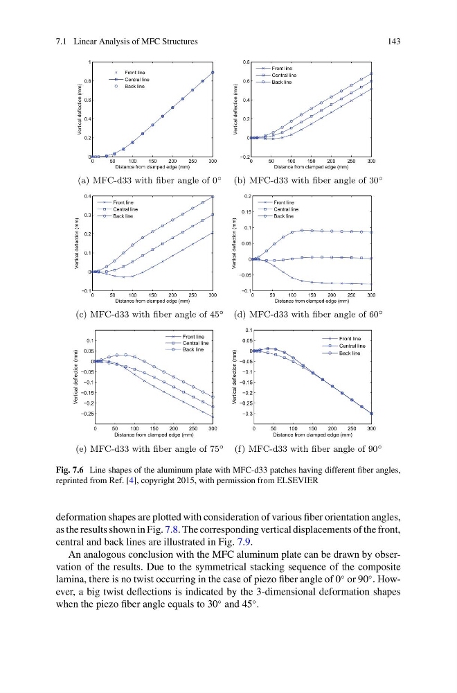
Fig. 7.6 Line shapes of the aluminum plate with MFC-d33 patches having different fiber angles,
reprinted from Ref. [4], copyright 2015, with permission from ELSEVIER
deformation shapes are plotted with consideration of various fiber orientation angles,
as the results shown in Fig. 7.8. The corresponding vertical displacements of the front,
central and back lines are illustrated in Fig. 7.9.
An analogous conclusion with the MFC aluminum plate can be drawn by observation of the results. Due to the symmetrical stacking sequence of the composite
lamina, there is no twist occurring in the case of piezo fiber angle of 0
◦ or 90
◦ . However, a big twist deflections is indicated by the 3-dimensional deformation shapes
when the piezo fiber angle equals to 30
◦ and 45
◦ .
143
0
50
100
150
200
250
300
0
0.2
0.4
0.6
0.8
1
Distance from clamped edge (mm)
Vertical deflection (mm)
Front line
Central line
Back line
(a) MFC-d33 with fiber angle of 0
◦
0
50
100
150
200
250
300
−0.2
0
0.2
0.4
0.6
0.8
Distance from clamped edge (mm)
Vertical deflection (mm)
Front line
Central line
Back line
(b) MFC-d33 with fiber angle of 30
◦
0
50
100
150
200
250
300
−0.1
0
0.1
0.2
0.3
0.4
Distance from clamped edge (mm)
Vertical deflection (mm)
Front line
Central line
Back line
(c) MFC-d33 with fiber angle of 45
◦
0
50
100
150
200
250
300
−0.1
−0.05
0
0.05
0.1
0.15
0.2
Distance from clamped edge (mm)
Vertical deflection (mm)
Front line
Central line
Back line
(d) MFC-d33 with fiber angle of 60
◦
0
50
100
150
200
250
300
−0.25
−0.2
−0.15
−0.1
−0.05
0
0.05
0.1
Distance from clamped edge (mm)
Vertical deflection (mm)
Front line
Central line
Back line
(e) MFC-d33 with fiber angle of 75
◦
0
50
100
150
200
250
300
−0.3
−0.25
−0.2
−0.15
−0.1
−0.05
0
0.05
0.1
Distance from clamped edge (mm)
Vertical deflection (mm)
Front line
Central line
Back line
(f) MFC-d33 with fiber angle of 90
◦
Fig. 7.6 Line shapes of the aluminum plate with MFC-d33 patches having different fiber angles,
reprinted from Ref. [4], copyright 2015, with permission from ELSEVIER
deformation shapes are plotted with consideration of various fiber orientation angles,
as the results shown in Fig. 7.8. The corresponding vertical displacements of the front,
central and back lines are illustrated in Fig. 7.9.
An analogous conclusion with the MFC aluminum plate can be drawn by observation of the results. Due to the symmetrical stacking sequence of the composite
lamina, there is no twist occurring in the case of piezo fiber angle of 0
◦ or 90
◦ . However, a big twist deflections is indicated by the 3-dimensional deformation shapes
when the piezo fiber angle equals to 30
◦ and 45
◦ .