

7.1 Linear Analysis of MFC Structures
141
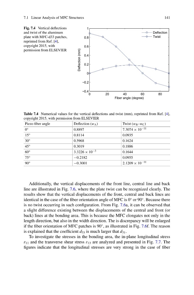
Fig. 7.4 Vertical deflections
and twist of the aluminum
plate with MFC-d33 patches,
reprinted from Ref. [4],
copyright 2015, with
permission from ELSEVIER
0
20
40
60
80
−0.4
−0.2
0
0.2
0.4
0.6
0.8
1
Fiber angle (degree)
Deflection (mm)
Deflection
Twist
Table 7.4 Numerical values for the vertical deflections and twist (mm), reprinted from Ref. [4],
copyright 2015, with permission from ELSEVIER
Piezo fiber angle
Deflection (w A )
Twist (w B –w C )
0 ◦
0.8897
7.3074 × 10 −11
15 ◦
0.8114
0.0935
30 ◦
0.5968
0.1624
45 ◦
0.3019
0.1886
60 ◦
3.3226 × 10 −3
0.1644
75 ◦
−0.2182
0.0955
90 ◦
−0.3001
2.1209 × 10 −11
Additionally, the vertical displacements of the front line, central line and back
line are illustrated in Fig. 7.6, where the plate twist can be recognized clearly. The
results show that the vertical displacements of the front, central and back lines are
identical in the case of the fiber orientation angle of MFC is 0
◦ or 90
◦ . Because there
is no twist occurring in such configuration. From Fig. 7.6a, it can be observed that
a slight difference existing between the displacements of the central and front (or
back) lines at the bonding area. This is because the MFC elongates not only in the
length direction, but also in the width direction. The is discrepancy will be enlarged
if the fiber orientation of MFC patches is 90
◦ , as illustrated in Fig. 7.6f. The reason
is explained that the coefficient d 33 is much larger that d 31 .
To investigate the stresses in the bonding area, the in-plane longitudinal stress
ε 11 and the transverse shear stress ε 13 are analyzed and presented in Fig. 7.7. The
figures indicate that the longitudinal stresses are very strong in the case of fiber
141
Fig. 7.4 Vertical deflections
and twist of the aluminum
plate with MFC-d33 patches,
reprinted from Ref. [4],
copyright 2015, with
permission from ELSEVIER
0
20
40
60
80
−0.4
−0.2
0
0.2
0.4
0.6
0.8
1
Fiber angle (degree)
Deflection (mm)
Deflection
Twist
Table 7.4 Numerical values for the vertical deflections and twist (mm), reprinted from Ref. [4],
copyright 2015, with permission from ELSEVIER
Piezo fiber angle
Deflection (w A )
Twist (w B –w C )
0 ◦
0.8897
7.3074 × 10 −11
15 ◦
0.8114
0.0935
30 ◦
0.5968
0.1624
45 ◦
0.3019
0.1886
60 ◦
3.3226 × 10 −3
0.1644
75 ◦
−0.2182
0.0955
90 ◦
−0.3001
2.1209 × 10 −11
Additionally, the vertical displacements of the front line, central line and back
line are illustrated in Fig. 7.6, where the plate twist can be recognized clearly. The
results show that the vertical displacements of the front, central and back lines are
identical in the case of the fiber orientation angle of MFC is 0
◦ or 90
◦ . Because there
is no twist occurring in such configuration. From Fig. 7.6a, it can be observed that
a slight difference existing between the displacements of the central and front (or
back) lines at the bonding area. This is because the MFC elongates not only in the
length direction, but also in the width direction. The is discrepancy will be enlarged
if the fiber orientation of MFC patches is 90
◦ , as illustrated in Fig. 7.6f. The reason
is explained that the coefficient d 33 is much larger that d 31 .
To investigate the stresses in the bonding area, the in-plane longitudinal stress
ε 11 and the transverse shear stress ε 13 are analyzed and presented in Fig. 7.7. The
figures indicate that the longitudinal stresses are very strong in the case of fiber