

84
5 Finite Element Formulations
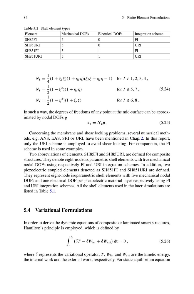
Table 5.1 Shell element types
Element
Mechanical DOFs
Electrical DOFs
Integration scheme
SH85FI
5
0
FI
SH85URI
5
0
URI
SH851FI
5
1
FI
SH851URI
5
1
URI
N I =
1
4
(1 + ξ I ξ)(1 + η I η)(ξ I ξ + η I η − 1) for I ∈ 1, 2, 3, 4 ,
N I =
1
2
(1 − ξ
2
)(1 + η I η)
for I ∈ 5, 7 ,
N I =
1
2
(1 − η
2
)(1 + ξ I ξ)
for I ∈ 6, 8 .
(5.24)
In such a way, the degrees of freedoms of any point at the mid-surface can be approximated by nodal DOFs q
v u = N u q.
(5.25)
Concerning the membrane and shear locking problems, several numerical methods, e.g. ANS, EAS, SRI or URI, have been mentioned in Chap. 2. In this report,
only the URI scheme is employed to avoid shear locking. For comparison, the FI
scheme is used in some examples.
Two abbreviations of elements, SH85FI and SH85URI, are defined for composite
structures. They denote eight-node isoparametric shell elements with five mechanical
nodal DOFs using respectively FI and URI integration schemes. In addition, two
piezoelectric coupled elements denoted as SH851FI and SH851URI are defined.
They represent eight-node isoparametric shell elements with five mechanical nodal
DOFs and one electrical DOF per piezoelectric material layer respectively using FI
and URI integration schemes. All the shell elements used in the later simulations are
listed in Table 5.1.
5.4 Variational Formulations
In order to derive the dynamic equations of composite or laminated smart structures,
Hamilton’s principle is employed, which is defined by
t 2
t 1
δT − δW int + δW ext
dt = 0 ,
(5.26)
where δ represents the variational operator, T , W int and W ext are the kinetic energy,
the internal work and the external work, respectively. For static equilibrium equation
5 Finite Element Formulations
Table 5.1 Shell element types
Element
Mechanical DOFs
Electrical DOFs
Integration scheme
SH85FI
5
0
FI
SH85URI
5
0
URI
SH851FI
5
1
FI
SH851URI
5
1
URI
N I =
1
4
(1 + ξ I ξ)(1 + η I η)(ξ I ξ + η I η − 1) for I ∈ 1, 2, 3, 4 ,
N I =
1
2
(1 − ξ
2
)(1 + η I η)
for I ∈ 5, 7 ,
N I =
1
2
(1 − η
2
)(1 + ξ I ξ)
for I ∈ 6, 8 .
(5.24)
In such a way, the degrees of freedoms of any point at the mid-surface can be approximated by nodal DOFs q
v u = N u q.
(5.25)
Concerning the membrane and shear locking problems, several numerical methods, e.g. ANS, EAS, SRI or URI, have been mentioned in Chap. 2. In this report,
only the URI scheme is employed to avoid shear locking. For comparison, the FI
scheme is used in some examples.
Two abbreviations of elements, SH85FI and SH85URI, are defined for composite
structures. They denote eight-node isoparametric shell elements with five mechanical
nodal DOFs using respectively FI and URI integration schemes. In addition, two
piezoelectric coupled elements denoted as SH851FI and SH851URI are defined.
They represent eight-node isoparametric shell elements with five mechanical nodal
DOFs and one electrical DOF per piezoelectric material layer respectively using FI
and URI integration schemes. All the shell elements used in the later simulations are
listed in Table 5.1.
5.4 Variational Formulations
In order to derive the dynamic equations of composite or laminated smart structures,
Hamilton’s principle is employed, which is defined by
t 2
t 1
δT − δW int + δW ext
dt = 0 ,
(5.26)
where δ represents the variational operator, T , W int and W ext are the kinetic energy,
the internal work and the external work, respectively. For static equilibrium equation