

(2) Gas Continuity Equation
Q m ¼ À
dM
dt
ð13:14Þ
where
M Hydrogen mass in cylinder (kg).
(3) Dynamic equation of pressure in cylinder
From Eq. (13.11), it is obtained that
dp
dt
¼
RT
l V
V À
b
l M
2 À
2
lV
ð Þ
2
M
2
6
4
3
7
5
dM
dt
ð13:15Þ
13.2.2.2 Analysis of Simulation Results
In the process of hydrogen transmission, assuming that the inlet pressure p i of the
pressure relief valve is equal to the hydrogen pressure of the cylinder, the initial
pressure is 35 MPa and 70 MPa respectively, and the outlet pressure p o of the
pressure relief valve is equal to 0.16 MPa.
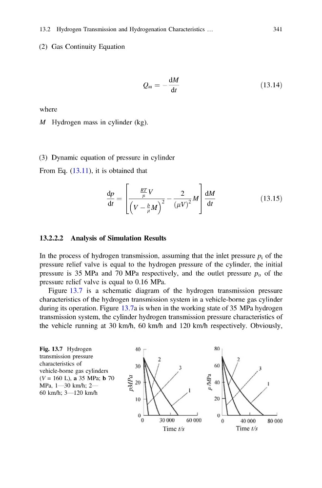
Figure 13.7 is a schematic diagram of the hydrogen transmission pressure
characteristics of the hydrogen transmission system in a vehicle-borne gas cylinder
during its operation. Figure 13.7a is when in the working state of 35 MPa hydrogen
transmission system, the cylinder hydrogen transmission pressure characteristics of
the vehicle running at 30 km/h, 60 km/h and 120 km/h respectively. Obviously,
Time t/s
Time t/s
pMPa
Fig. 13.7 Hydrogen
transmission pressure
characteristics of
vehicle-borne gas cylinders
(V = 160 L), a 35 MPa; b 70
MPa, 1—30 km/h; 2—
60 km/h; 3—120 km/h
13.2 Hydrogen Transmission and Hydrogenation Characteristics …
341
Q m ¼ À
dM
dt
ð13:14Þ
where
M Hydrogen mass in cylinder (kg).
(3) Dynamic equation of pressure in cylinder
From Eq. (13.11), it is obtained that
dp
dt
¼
RT
l V
V À
b
l M
2 À
2
lV
ð Þ
2
M
2
6
4
3
7
5
dM
dt
ð13:15Þ
13.2.2.2 Analysis of Simulation Results
In the process of hydrogen transmission, assuming that the inlet pressure p i of the
pressure relief valve is equal to the hydrogen pressure of the cylinder, the initial
pressure is 35 MPa and 70 MPa respectively, and the outlet pressure p o of the
pressure relief valve is equal to 0.16 MPa.
Figure 13.7 is a schematic diagram of the hydrogen transmission pressure
characteristics of the hydrogen transmission system in a vehicle-borne gas cylinder
during its operation. Figure 13.7a is when in the working state of 35 MPa hydrogen
transmission system, the cylinder hydrogen transmission pressure characteristics of
the vehicle running at 30 km/h, 60 km/h and 120 km/h respectively. Obviously,
Time t/s
Time t/s
pMPa
Fig. 13.7 Hydrogen
transmission pressure
characteristics of
vehicle-borne gas cylinders
(V = 160 L), a 35 MPa; b 70
MPa, 1—30 km/h; 2—
60 km/h; 3—120 km/h
13.2 Hydrogen Transmission and Hydrogenation Characteristics …
341