

13.2.2 Hydrogen Transmission Pressure Characteristics
of Vehicle-Borne Gas Cylinders
13.2.2.1 Mathematical Model
The working process of hydrogen storage cylinder of hydrogen fuel cell vehicle is
approximated as a constant volume and variable mass charging and discharging
process. The process of hydrogen transmissionation in vehicle-borne cylinder is that
the cylinder is discharged to fuel cell through a throttle and decompression valve,
and the outlet pressure of the decompression valve is maintained at 0.16 MPa of the
working pressure required by the battery stack. Here, the model of pressure relief
valve is simplified to an adjustable flow valve with constant outlet pressure.
The working time of continuous hydrogen transmissionation in cylinders of
vehicle-borne hydrogen transmission system is generally long. In order to simplify
the calculation, it is assumed that the gas in the bottle has sufficient heat exchange
with the outside world, which is an isothermal hydrogen transmission process.
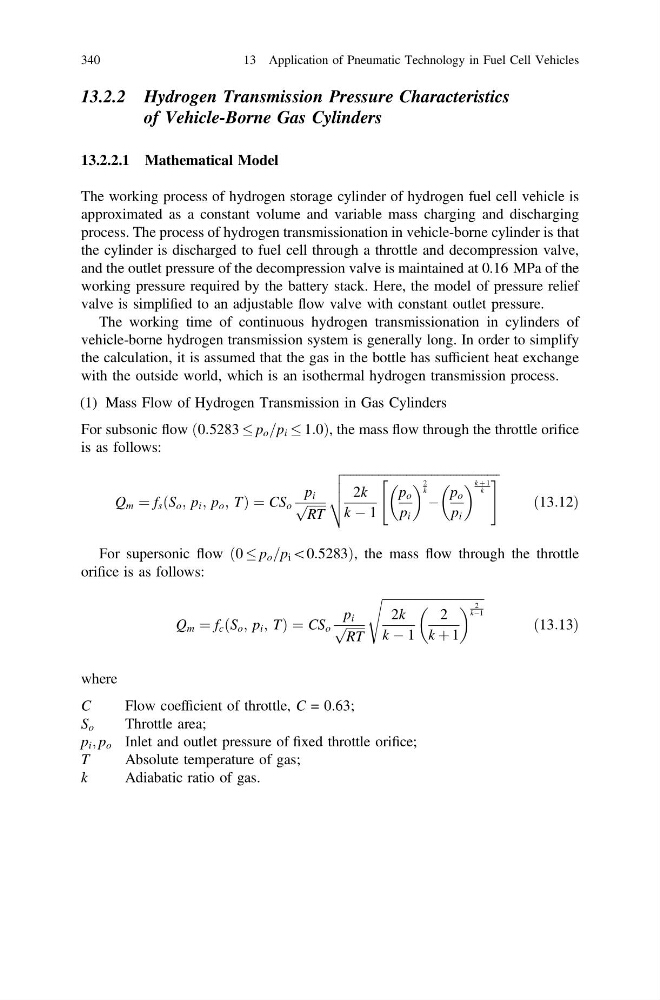
(1) Mass Flow of Hydrogen Transmission in Gas Cylinders
For subsonic flow 0:5283 p o =p i 1:0
ð
Þ , the mass flow through the throttle orifice
is as follows:
Q m ¼ f s S o ; p i ; p o ; T
ð
Þ¼CS o
p i
ffiffiffiffiffiffi
RT
p
ffiffiffiffiffiffiffiffiffiffiffiffiffiffiffiffiffiffiffiffiffiffiffiffiffiffiffiffiffiffiffiffiffiffiffiffiffiffiffiffiffiffiffiffiffiffiffiffiffiffi
2k
k À 1
p o
p i
2
k À
p o
p i
k þ 1
k
"
#
v
u
u
t
ð13:12Þ
For supersonic flow ð0 p o =p i \0:5283Þ, the mass flow through the throttle
orifice is as follows:
Q m ¼ f c S o ; p i ; T
ð
Þ¼CS o
p i
ffiffiffiffiffiffi
RT
p
ffiffiffiffiffiffiffiffiffiffiffiffiffiffiffiffiffiffiffiffiffiffiffiffiffiffiffiffiffiffiffiffiffi
2k
k À 1
2
k þ 1
2
kÀ1
s
ð13:13Þ
where
C
Flow coefficient of throttle, C = 0.63;
S o
Throttle area;
p i ; p o Inlet and outlet pressure of fixed throttle orifice;
T
Absolute temperature of gas;
k
Adiabatic ratio of gas.
340
13 Application of Pneumatic Technology in Fuel Cell Vehicles
of Vehicle-Borne Gas Cylinders
13.2.2.1 Mathematical Model
The working process of hydrogen storage cylinder of hydrogen fuel cell vehicle is
approximated as a constant volume and variable mass charging and discharging
process. The process of hydrogen transmissionation in vehicle-borne cylinder is that
the cylinder is discharged to fuel cell through a throttle and decompression valve,
and the outlet pressure of the decompression valve is maintained at 0.16 MPa of the
working pressure required by the battery stack. Here, the model of pressure relief
valve is simplified to an adjustable flow valve with constant outlet pressure.
The working time of continuous hydrogen transmissionation in cylinders of
vehicle-borne hydrogen transmission system is generally long. In order to simplify
the calculation, it is assumed that the gas in the bottle has sufficient heat exchange
with the outside world, which is an isothermal hydrogen transmission process.
(1) Mass Flow of Hydrogen Transmission in Gas Cylinders
For subsonic flow 0:5283 p o =p i 1:0
ð
Þ , the mass flow through the throttle orifice
is as follows:
Q m ¼ f s S o ; p i ; p o ; T
ð
Þ¼CS o
p i
ffiffiffiffiffiffi
RT
p
ffiffiffiffiffiffiffiffiffiffiffiffiffiffiffiffiffiffiffiffiffiffiffiffiffiffiffiffiffiffiffiffiffiffiffiffiffiffiffiffiffiffiffiffiffiffiffiffiffiffi
2k
k À 1
p o
p i
2
k À
p o
p i
k þ 1
k
"
#
v
u
u
t
ð13:12Þ
For supersonic flow ð0 p o =p i \0:5283Þ, the mass flow through the throttle
orifice is as follows:
Q m ¼ f c S o ; p i ; T
ð
Þ¼CS o
p i
ffiffiffiffiffiffi
RT
p
ffiffiffiffiffiffiffiffiffiffiffiffiffiffiffiffiffiffiffiffiffiffiffiffiffiffiffiffiffiffiffiffiffi
2k
k À 1
2
k þ 1
2
kÀ1
s
ð13:13Þ
where
C
Flow coefficient of throttle, C = 0.63;
S o
Throttle area;
p i ; p o Inlet and outlet pressure of fixed throttle orifice;
T
Absolute temperature of gas;
k
Adiabatic ratio of gas.
340
13 Application of Pneumatic Technology in Fuel Cell Vehicles