

pipeline and low-pressure accumulator on descending speed and strike energy is
analyzed. The law of influence of return pipeline and accumulator parameters on
driving speed and strike energy of hydraulic hammer is obtained. This section
mainly analyzes the influence of pressure loss of oil return pipeline and its solution.
It also analyzes the working process, hammer speed and strike energy with and
without low-pressure accumulator in the descending process. It provides theoretical
basis for engineering application and new product development.
12.4.1 Principle of Rapid Piling
The working process of pneumatic–hydraulic composite pile hammer can be
divided into four working stages.
12.4.1.1 Rising Stage
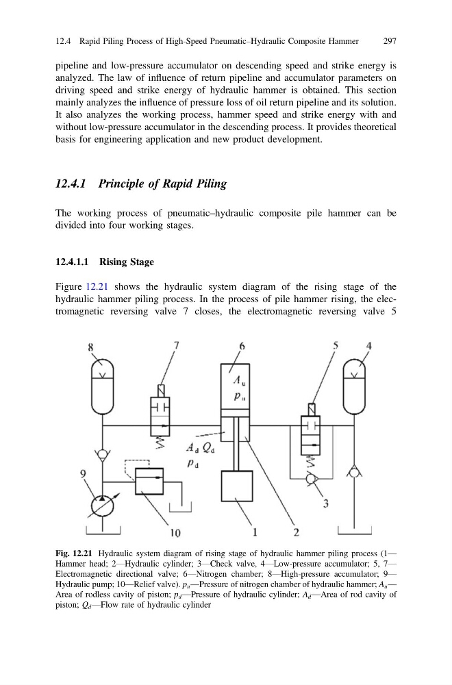
Figure 12.21 shows the hydraulic system diagram of the rising stage of the
hydraulic hammer piling process. In the process of pile hammer rising, the electromagnetic reversing valve 7 closes, the electromagnetic reversing valve 5
Fig. 12.21 Hydraulic system diagram of rising stage of hydraulic hammer piling process (1—
Hammer head; 2—Hydraulic cylinder; 3—Check valve, 4—Low-pressure accumulator; 5, 7—
Electromagnetic directional valve; 6—Nitrogen chamber; 8—High-pressure accumulator; 9—
Hydraulic pump; 10—Relief valve). p u —Pressure of nitrogen chamber of hydraulic hammer; A u —
Area of rodless cavity of piston; p d —Pressure of hydraulic cylinder; A d —Area of rod cavity of
piston; Q d —Flow rate of hydraulic cylinder
12.4 Rapid Piling Process of High-Speed Pneumatic–Hydraulic Composite Hammer
297
analyzed. The law of influence of return pipeline and accumulator parameters on
driving speed and strike energy of hydraulic hammer is obtained. This section
mainly analyzes the influence of pressure loss of oil return pipeline and its solution.
It also analyzes the working process, hammer speed and strike energy with and
without low-pressure accumulator in the descending process. It provides theoretical
basis for engineering application and new product development.
12.4.1 Principle of Rapid Piling
The working process of pneumatic–hydraulic composite pile hammer can be
divided into four working stages.
12.4.1.1 Rising Stage
Figure 12.21 shows the hydraulic system diagram of the rising stage of the
hydraulic hammer piling process. In the process of pile hammer rising, the electromagnetic reversing valve 7 closes, the electromagnetic reversing valve 5
Fig. 12.21 Hydraulic system diagram of rising stage of hydraulic hammer piling process (1—
Hammer head; 2—Hydraulic cylinder; 3—Check valve, 4—Low-pressure accumulator; 5, 7—
Electromagnetic directional valve; 6—Nitrogen chamber; 8—High-pressure accumulator; 9—
Hydraulic pump; 10—Relief valve). p u —Pressure of nitrogen chamber of hydraulic hammer; A u —
Area of rodless cavity of piston; p d —Pressure of hydraulic cylinder; A d —Area of rod cavity of
piston; Q d —Flow rate of hydraulic cylinder
12.4 Rapid Piling Process of High-Speed Pneumatic–Hydraulic Composite Hammer
297