

disconnects, the hydraulic pump 9 and the high-pressure accumulator 8 jointly
output the hydraulic oil, and through the reversing valve 7 enters the lower chamber
of the cylinder, the hammer head accelerates to rise. In the rising stage, the
hydraulic oil of the low-pressure accumulator 4 flows back to the tank through the
long pipeline of the return pipe.
12.4.1.2 Inertial Rising Stage
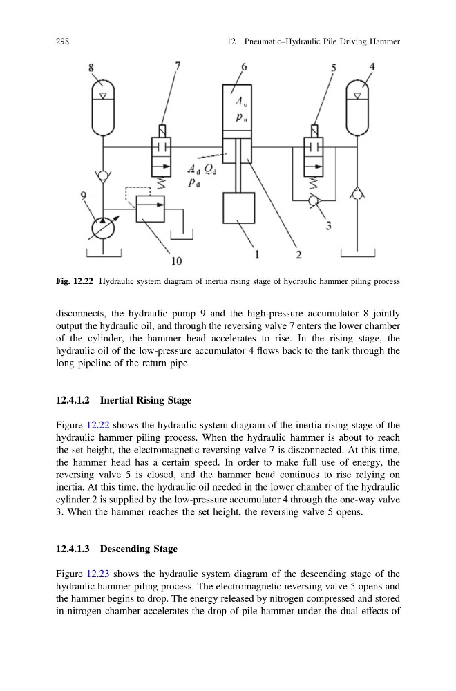
Figure 12.22 shows the hydraulic system diagram of the inertia rising stage of the
hydraulic hammer piling process. When the hydraulic hammer is about to reach
the set height, the electromagnetic reversing valve 7 is disconnected. At this time,
the hammer head has a certain speed. In order to make full use of energy, the
reversing valve 5 is closed, and the hammer head continues to rise relying on
inertia. At this time, the hydraulic oil needed in the lower chamber of the hydraulic
cylinder 2 is supplied by the low-pressure accumulator 4 through the one-way valve
3. When the hammer reaches the set height, the reversing valve 5 opens.
12.4.1.3 Descending Stage
Figure 12.23 shows the hydraulic system diagram of the descending stage of the
hydraulic hammer piling process. The electromagnetic reversing valve 5 opens and
the hammer begins to drop. The energy released by nitrogen compressed and stored
in nitrogen chamber accelerates the drop of pile hammer under the dual effects of
Fig. 12.22 Hydraulic system diagram of inertia rising stage of hydraulic hammer piling process
298
12 Pneumatic–Hydraulic Pile Driving Hammer
output the hydraulic oil, and through the reversing valve 7 enters the lower chamber
of the cylinder, the hammer head accelerates to rise. In the rising stage, the
hydraulic oil of the low-pressure accumulator 4 flows back to the tank through the
long pipeline of the return pipe.
12.4.1.2 Inertial Rising Stage
Figure 12.22 shows the hydraulic system diagram of the inertia rising stage of the
hydraulic hammer piling process. When the hydraulic hammer is about to reach
the set height, the electromagnetic reversing valve 7 is disconnected. At this time,
the hammer head has a certain speed. In order to make full use of energy, the
reversing valve 5 is closed, and the hammer head continues to rise relying on
inertia. At this time, the hydraulic oil needed in the lower chamber of the hydraulic
cylinder 2 is supplied by the low-pressure accumulator 4 through the one-way valve
3. When the hammer reaches the set height, the reversing valve 5 opens.
12.4.1.3 Descending Stage
Figure 12.23 shows the hydraulic system diagram of the descending stage of the
hydraulic hammer piling process. The electromagnetic reversing valve 5 opens and
the hammer begins to drop. The energy released by nitrogen compressed and stored
in nitrogen chamber accelerates the drop of pile hammer under the dual effects of
Fig. 12.22 Hydraulic system diagram of inertia rising stage of hydraulic hammer piling process
298
12 Pneumatic–Hydraulic Pile Driving Hammer