

the velocity can be close to zero. The rising acceleration first decreases and then
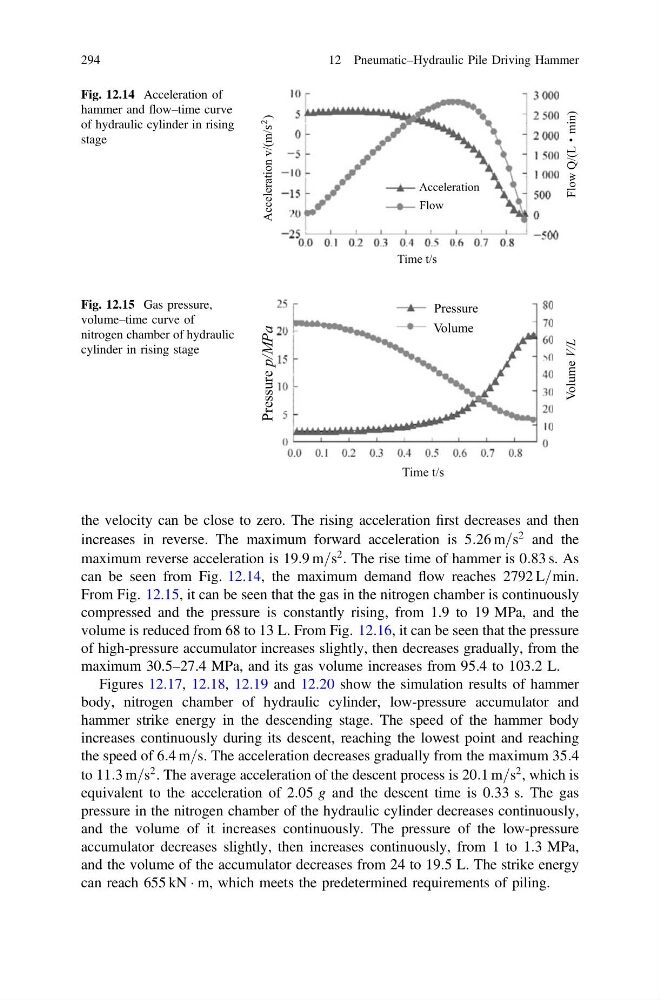
increases in reverse. The maximum forward acceleration is 5:26 m=s
2 and the
maximum reverse acceleration is 19:9 m=s
2 . The rise time of hammer is 0:83 s. As
can be seen from Fig. 12.14, the maximum demand flow reaches 2792 L=min.
From Fig. 12.15, it can be seen that the gas in the nitrogen chamber is continuously
compressed and the pressure is constantly rising, from 1.9 to 19 MPa, and the
volume is reduced from 68 to 13 L. From Fig. 12.16, it can be seen that the pressure
of high-pressure accumulator increases slightly, then decreases gradually, from the
maximum 30.5–27.4 MPa, and its gas volume increases from 95.4 to 103.2 L.
Figures 12.17, 12.18, 12.19 and 12.20 show the simulation results of hammer
body, nitrogen chamber of hydraulic cylinder, low-pressure accumulator and
hammer strike energy in the descending stage. The speed of the hammer body
increases continuously during its descent, reaching the lowest point and reaching
the speed of 6:4 m=s. The acceleration decreases gradually from the maximum 35:4
to 11:3 m=s
2 . The average acceleration of the descent process is 20:1 m=s
2 , which is
equivalent to the acceleration of 2.05 g and the descent time is 0.33 s. The gas
pressure in the nitrogen chamber of the hydraulic cylinder decreases continuously,
and the volume of it increases continuously. The pressure of the low-pressure
accumulator decreases slightly, then increases continuously, from 1 to 1.3 MPa,
and the volume of the accumulator decreases from 24 to 19.5 L. The strike energy
can reach 655 kN Á m, which meets the predetermined requirements of piling.
Time t/s
Acceleration v/(m/s
2
)
Flow Q/(L
min)
Acceleration
Flow
Fig. 12.14 Acceleration of
hammer and flow–time curve
of hydraulic cylinder in rising
stage
Time t/s
Pressure p/MPa
Volume V/L
Pressure
Volume
Fig. 12.15 Gas pressure,
volume–time curve of
nitrogen chamber of hydraulic
cylinder in rising stage
294
12 Pneumatic–Hydraulic Pile Driving Hammer
increases in reverse. The maximum forward acceleration is 5:26 m=s
2 and the
maximum reverse acceleration is 19:9 m=s
2 . The rise time of hammer is 0:83 s. As
can be seen from Fig. 12.14, the maximum demand flow reaches 2792 L=min.
From Fig. 12.15, it can be seen that the gas in the nitrogen chamber is continuously
compressed and the pressure is constantly rising, from 1.9 to 19 MPa, and the
volume is reduced from 68 to 13 L. From Fig. 12.16, it can be seen that the pressure
of high-pressure accumulator increases slightly, then decreases gradually, from the
maximum 30.5–27.4 MPa, and its gas volume increases from 95.4 to 103.2 L.
Figures 12.17, 12.18, 12.19 and 12.20 show the simulation results of hammer
body, nitrogen chamber of hydraulic cylinder, low-pressure accumulator and
hammer strike energy in the descending stage. The speed of the hammer body
increases continuously during its descent, reaching the lowest point and reaching
the speed of 6:4 m=s. The acceleration decreases gradually from the maximum 35:4
to 11:3 m=s
2 . The average acceleration of the descent process is 20:1 m=s
2 , which is
equivalent to the acceleration of 2.05 g and the descent time is 0.33 s. The gas
pressure in the nitrogen chamber of the hydraulic cylinder decreases continuously,
and the volume of it increases continuously. The pressure of the low-pressure
accumulator decreases slightly, then increases continuously, from 1 to 1.3 MPa,
and the volume of the accumulator decreases from 24 to 19.5 L. The strike energy
can reach 655 kN Á m, which meets the predetermined requirements of piling.
Time t/s
Acceleration v/(m/s
2
)
Flow Q/(L
min)
Acceleration
Flow
Fig. 12.14 Acceleration of
hammer and flow–time curve
of hydraulic cylinder in rising
stage
Time t/s
Pressure p/MPa
Volume V/L
Pressure
Volume
Fig. 12.15 Gas pressure,
volume–time curve of
nitrogen chamber of hydraulic
cylinder in rising stage
294
12 Pneumatic–Hydraulic Pile Driving Hammer