

The dynamic equation of the hammer body is
mg þ p u A u À p d A d ¼ m
d
2 y
dt 2 þ B
dy
dt
þ k y þ y 0
ð
Þ
ð12:35Þ
12.3.2.3 Strike Energy
Assuming that the friction loss and the energy loss during impact are not taken into
account when the hammer drops, the kinetic energy of the hammer drops is converted into the strike energy E, the following equation is satisfied:
E ¼
1
2
mv
2
d g
ð12:36Þ
where g—Piling efficiency.
12.3.3 Characteristic and Example of Pneumatic–Hydraulic
Composite Pile Driving Hammer
Software Simulink is used to simulate the rising process of hammer body from
Eqs. (12.24)*(12.32) and initial conditions. Equations (12.28), (12.30)*(12.36)
can be used to simulate the falling process of hammer. The basic parameters of the
simulation are the flow rate of the hydraulic pump is 1400 L=min, the initial
pressure of the hydraulic cylinder is 29.5 MPa, the maximum stroke of the hammer
head is 1.33 m, the minimum working pressure of the nitrogen chamber is 1.9 MPa,
and the maximum volume is 68.2 L.
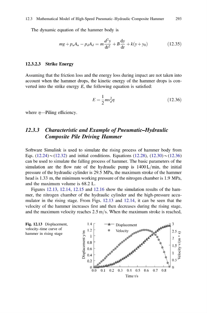
Figures 12.13, 12.14, 12.15 and 12.16 show the simulation results of the hammer, the nitrogen chamber of the hydraulic cylinder and the high-pressure accumulator in the rising stage. From Figs. 12.13 and 12.14, it can be seen that the
velocity of the hammer increases first and then decreases during the rising stage,
and the maximum velocity reaches 2:5 m=s. When the maximum stroke is reached,
Time t/s
Displacement y/m
Displacement
Velocity
Velocity v/(m s)
Fig. 12.13 Displacement,
velocity–time curve of
hammer in rising stage
12.3 Mathematical Model of High-Speed Pneumatic–Hydraulic Composite Hammer
293
mg þ p u A u À p d A d ¼ m
d
2 y
dt 2 þ B
dy
dt
þ k y þ y 0
ð
Þ
ð12:35Þ
12.3.2.3 Strike Energy
Assuming that the friction loss and the energy loss during impact are not taken into
account when the hammer drops, the kinetic energy of the hammer drops is converted into the strike energy E, the following equation is satisfied:
E ¼
1
2
mv
2
d g
ð12:36Þ
where g—Piling efficiency.
12.3.3 Characteristic and Example of Pneumatic–Hydraulic
Composite Pile Driving Hammer
Software Simulink is used to simulate the rising process of hammer body from
Eqs. (12.24)*(12.32) and initial conditions. Equations (12.28), (12.30)*(12.36)
can be used to simulate the falling process of hammer. The basic parameters of the
simulation are the flow rate of the hydraulic pump is 1400 L=min, the initial
pressure of the hydraulic cylinder is 29.5 MPa, the maximum stroke of the hammer
head is 1.33 m, the minimum working pressure of the nitrogen chamber is 1.9 MPa,
and the maximum volume is 68.2 L.
Figures 12.13, 12.14, 12.15 and 12.16 show the simulation results of the hammer, the nitrogen chamber of the hydraulic cylinder and the high-pressure accumulator in the rising stage. From Figs. 12.13 and 12.14, it can be seen that the
velocity of the hammer increases first and then decreases during the rising stage,
and the maximum velocity reaches 2:5 m=s. When the maximum stroke is reached,
Time t/s
Displacement y/m
Displacement
Velocity
Velocity v/(m s)
Fig. 12.13 Displacement,
velocity–time curve of
hammer in rising stage
12.3 Mathematical Model of High-Speed Pneumatic–Hydraulic Composite Hammer
293