

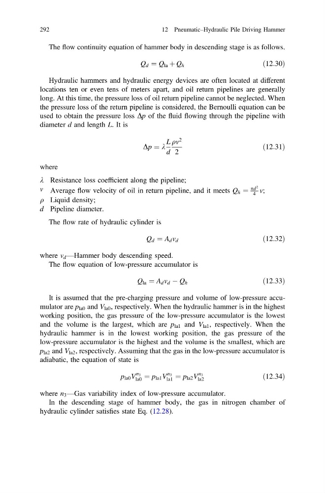
The flow continuity equation of hammer body in descending stage is as follows.
Q d ¼ Q la þ Q h
ð12:30Þ
Hydraulic hammers and hydraulic energy devices are often located at different
locations ten or even tens of meters apart, and oil return pipelines are generally
long. At this time, the pressure loss of oil return pipeline cannot be neglected. When
the pressure loss of the return pipeline is considered, the Bernoulli equation can be
used to obtain the pressure loss Dp of the fluid flowing through the pipeline with
diameter d and length L. It is
Dp ¼ k
L
d
qv
2
2
ð12:31Þ
where
k Resistance loss coefficient along the pipeline;
v Average flow velocity of oil in return pipeline, and it meets Q h ¼
pd
2
4 v;
q Liquid density;
d Pipeline diameter.
The flow rate of hydraulic cylinder is
Q d ¼ A d v d
ð12:32Þ
where v d —Hammer body descending speed.
The flow equation of low-pressure accumulator is
Q la ¼ A d v d À Q h
ð12:33Þ
It is assumed that the pre-charging pressure and volume of low-pressure accumulator are p la0 and V la0 , respectively. When the hydraulic hammer is in the highest
working position, the gas pressure of the low-pressure accumulator is the lowest
and the volume is the largest, which are p la1 and V la1 , respectively. When the
hydraulic hammer is in the lowest working position, the gas pressure of the
low-pressure accumulator is the highest and the volume is the smallest, which are
p la2 and V la2 , respectively. Assuming that the gas in the low-pressure accumulator is
adiabatic, the equation of state is
p la0 V
n 3
la0 ¼ p la1 V
n 3
la1 ¼ p la2 V
n 3
la2
ð12:34Þ
where n 3 —Gas variability index of low-pressure accumulator.
In the descending stage of hammer body, the gas in nitrogen chamber of
hydraulic cylinder satisfies state Eq. (12.28).
292
12 Pneumatic–Hydraulic Pile Driving Hammer
Q d ¼ Q la þ Q h
ð12:30Þ
Hydraulic hammers and hydraulic energy devices are often located at different
locations ten or even tens of meters apart, and oil return pipelines are generally
long. At this time, the pressure loss of oil return pipeline cannot be neglected. When
the pressure loss of the return pipeline is considered, the Bernoulli equation can be
used to obtain the pressure loss Dp of the fluid flowing through the pipeline with
diameter d and length L. It is
Dp ¼ k
L
d
qv
2
2
ð12:31Þ
where
k Resistance loss coefficient along the pipeline;
v Average flow velocity of oil in return pipeline, and it meets Q h ¼
pd
2
4 v;
q Liquid density;
d Pipeline diameter.
The flow rate of hydraulic cylinder is
Q d ¼ A d v d
ð12:32Þ
where v d —Hammer body descending speed.
The flow equation of low-pressure accumulator is
Q la ¼ A d v d À Q h
ð12:33Þ
It is assumed that the pre-charging pressure and volume of low-pressure accumulator are p la0 and V la0 , respectively. When the hydraulic hammer is in the highest
working position, the gas pressure of the low-pressure accumulator is the lowest
and the volume is the largest, which are p la1 and V la1 , respectively. When the
hydraulic hammer is in the lowest working position, the gas pressure of the
low-pressure accumulator is the highest and the volume is the smallest, which are
p la2 and V la2 , respectively. Assuming that the gas in the low-pressure accumulator is
adiabatic, the equation of state is
p la0 V
n 3
la0 ¼ p la1 V
n 3
la1 ¼ p la2 V
n 3
la2
ð12:34Þ
where n 3 —Gas variability index of low-pressure accumulator.
In the descending stage of hammer body, the gas in nitrogen chamber of
hydraulic cylinder satisfies state Eq. (12.28).
292
12 Pneumatic–Hydraulic Pile Driving Hammer