

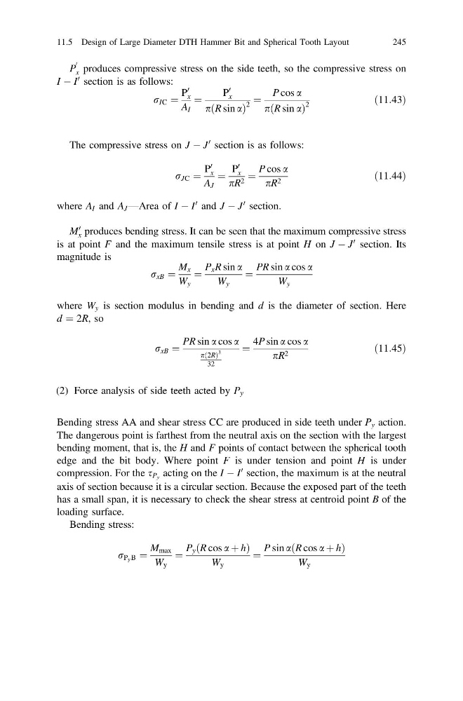
P
0
x produces compressive stress on the side teeth, so the compressive stress on
I À I
0 section is as follows:
r IC ¼
P
0
x
A I
¼
P
0
x
p R sin a
ð
Þ
2
¼
P cos a
p R sin a
ð
Þ
2
ð11:43Þ
The compressive stress on J À J
0 section is as follows:
r JC ¼
P
0
x
A J
¼
P
0
x
pR 2 ¼
P cos a
pR 2
ð11:44Þ
where A I and A J —Area of I À I
0 and J À J
0 section.
M
0
x produces bending stress. It can be seen that the maximum compressive stress
is at point F and the maximum tensile stress is at point H on J À J
0 section. Its
magnitude is
r xB ¼
M x
W y
¼
P x R sin a
W y
¼
PR sin a cos a
W y
where W y is section modulus in bending and d is the diameter of section. Here
d ¼ 2R, so
r xB ¼
PR sin a cos a
p 2R
ð Þ
3
32
¼
4P sin a cos a
pR 2
ð11:45Þ
(2) Force analysis of side teeth acted by P y
Bending stress AA and shear stress CC are produced in side teeth under P y action.
The dangerous point is farthest from the neutral axis on the section with the largest
bending moment, that is, the H and F points of contact between the spherical tooth
edge and the bit body. Where point F is under tension and point H is under
compression. For the s P y acting on the I À I
0 section, the maximum is at the neutral
axis of section because it is a circular section. Because the exposed part of the teeth
has a small span, it is necessary to check the shear stress at centroid point B of the
loading surface.
Bending stress:
r P y B ¼
M max
W y
¼
P y R cos a þ h
ð
Þ
W y
¼
P sin a R cos a þ h
ð
Þ
W y
11.5 Design of Large Diameter DTH Hammer Bit and Spherical Tooth Layout
245
0
x produces compressive stress on the side teeth, so the compressive stress on
I À I
0 section is as follows:
r IC ¼
P
0
x
A I
¼
P
0
x
p R sin a
ð
Þ
2
¼
P cos a
p R sin a
ð
Þ
2
ð11:43Þ
The compressive stress on J À J
0 section is as follows:
r JC ¼
P
0
x
A J
¼
P
0
x
pR 2 ¼
P cos a
pR 2
ð11:44Þ
where A I and A J —Area of I À I
0 and J À J
0 section.
M
0
x produces bending stress. It can be seen that the maximum compressive stress
is at point F and the maximum tensile stress is at point H on J À J
0 section. Its
magnitude is
r xB ¼
M x
W y
¼
P x R sin a
W y
¼
PR sin a cos a
W y
where W y is section modulus in bending and d is the diameter of section. Here
d ¼ 2R, so
r xB ¼
PR sin a cos a
p 2R
ð Þ
3
32
¼
4P sin a cos a
pR 2
ð11:45Þ
(2) Force analysis of side teeth acted by P y
Bending stress AA and shear stress CC are produced in side teeth under P y action.
The dangerous point is farthest from the neutral axis on the section with the largest
bending moment, that is, the H and F points of contact between the spherical tooth
edge and the bit body. Where point F is under tension and point H is under
compression. For the s P y acting on the I À I
0 section, the maximum is at the neutral
axis of section because it is a circular section. Because the exposed part of the teeth
has a small span, it is necessary to check the shear stress at centroid point B of the
loading surface.
Bending stress:
r P y B ¼
M max
W y
¼
P y R cos a þ h
ð
Þ
W y
¼
P sin a R cos a þ h
ð
Þ
W y
11.5 Design of Large Diameter DTH Hammer Bit and Spherical Tooth Layout
245