

11.4 Dynamic Process and Theoretical Model of Large
Diameter Pneumatic DTH Hammer
11.4.1 Dynamic Process of Large Diameter Pneumatic DTH
Hammer
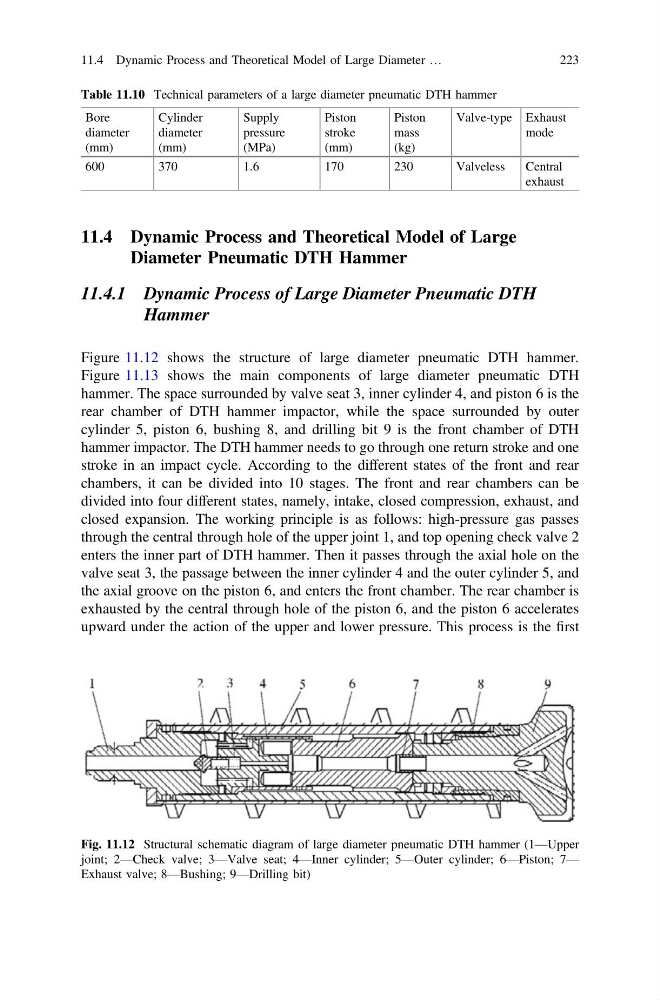
Figure 11.12 shows the structure of large diameter pneumatic DTH hammer.
Figure 11.13 shows the main components of large diameter pneumatic DTH
hammer. The space surrounded by valve seat 3, inner cylinder 4, and piston 6 is the
rear chamber of DTH hammer impactor, while the space surrounded by outer
cylinder 5, piston 6, bushing 8, and drilling bit 9 is the front chamber of DTH
hammer impactor. The DTH hammer needs to go through one return stroke and one
stroke in an impact cycle. According to the different states of the front and rear
chambers, it can be divided into 10 stages. The front and rear chambers can be
divided into four different states, namely, intake, closed compression, exhaust, and
closed expansion. The working principle is as follows: high-pressure gas passes
through the central through hole of the upper joint 1, and top opening check valve 2
enters the inner part of DTH hammer. Then it passes through the axial hole on the
valve seat 3, the passage between the inner cylinder 4 and the outer cylinder 5, and
the axial groove on the piston 6, and enters the front chamber. The rear chamber is
exhausted by the central through hole of the piston 6, and the piston 6 accelerates
upward under the action of the upper and lower pressure. This process is the first
Table 11.10 Technical parameters of a large diameter pneumatic DTH hammer
Bore
diameter
(mm)
Cylinder
diameter
(mm)
Supply
pressure
(MPa)
Piston
stroke
(mm)
Piston
mass
(kg)
Valve-type Exhaust
mode
600
370
1.6
170
230
Valveless
Central
exhaust
Fig. 11.12 Structural schematic diagram of large diameter pneumatic DTH hammer (1—Upper
joint; 2—Check valve; 3—Valve seat; 4—Inner cylinder; 5—Outer cylinder; 6—Piston; 7—
Exhaust valve; 8—Bushing; 9—Drilling bit)
11.4 Dynamic Process and Theoretical Model of Large Diameter …
223
Diameter Pneumatic DTH Hammer
11.4.1 Dynamic Process of Large Diameter Pneumatic DTH
Hammer
Figure 11.12 shows the structure of large diameter pneumatic DTH hammer.
Figure 11.13 shows the main components of large diameter pneumatic DTH
hammer. The space surrounded by valve seat 3, inner cylinder 4, and piston 6 is the
rear chamber of DTH hammer impactor, while the space surrounded by outer
cylinder 5, piston 6, bushing 8, and drilling bit 9 is the front chamber of DTH
hammer impactor. The DTH hammer needs to go through one return stroke and one
stroke in an impact cycle. According to the different states of the front and rear
chambers, it can be divided into 10 stages. The front and rear chambers can be
divided into four different states, namely, intake, closed compression, exhaust, and
closed expansion. The working principle is as follows: high-pressure gas passes
through the central through hole of the upper joint 1, and top opening check valve 2
enters the inner part of DTH hammer. Then it passes through the axial hole on the
valve seat 3, the passage between the inner cylinder 4 and the outer cylinder 5, and
the axial groove on the piston 6, and enters the front chamber. The rear chamber is
exhausted by the central through hole of the piston 6, and the piston 6 accelerates
upward under the action of the upper and lower pressure. This process is the first
Table 11.10 Technical parameters of a large diameter pneumatic DTH hammer
Bore
diameter
(mm)
Cylinder
diameter
(mm)
Supply
pressure
(MPa)
Piston
stroke
(mm)
Piston
mass
(kg)
Valve-type Exhaust
mode
600
370
1.6
170
230
Valveless
Central
exhaust
Fig. 11.12 Structural schematic diagram of large diameter pneumatic DTH hammer (1—Upper
joint; 2—Check valve; 3—Valve seat; 4—Inner cylinder; 5—Outer cylinder; 6—Piston; 7—
Exhaust valve; 8—Bushing; 9—Drilling bit)
11.4 Dynamic Process and Theoretical Model of Large Diameter …
223