

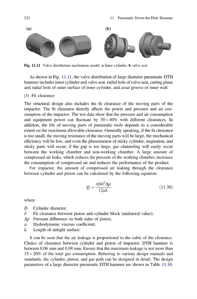
As shown in Fig. 11.11, the valve distribution of large diameter pneumatic DTH
hammer includes inner cylinder and valve seat, radial hole of valve seat, cutting plane
and radial hole of outer surface of inner cylinder, and axial groove of inner wall.
(3) Fit clearance
The structural design also includes the fit clearance of the moving parts of the
impactor. The fit clearance directly affects the power and pressure and air consumption of the impactor. The test data show that the pressure and air consumption
and equipment power can fluctuate by 30*40% with different clearances. In
addition, the life of moving parts of pneumatic tools depends to a considerable
extent on the maximum allowable clearance. Generally speaking, if the fit clearance
is too small, the moving resistance of the moving parts will be large, the mechanical
efficiency will be low, and even the phenomenon of sticky cylinder, stagnation, and
sticky parts will occur; if the gap is too large, gas channeling will easily occur
between the working chamber and non-working chamber. A large amount of
compressed air leaks, which reduces the pressure of the working chamber, increases
the consumption of compressed air and reduces the performance of the product.
For impactor, the amount of compressed air leaking through the clearance
between cylinder and piston can be calculated by the following equation:
Q ¼
pDd
2
Dp
12lL
ð11:30Þ
where
D Cylinder diameter;
d
Fit clearance between piston and cylinder block (unilateral value);
Dp Pressure difference on both sides of piston;
l Hydrodynamic viscous coefficient;
L Length of airtight surface.
It can be seen that the air leakage is proportional to the cubic of the clearance.
Choice of clearance between cylinder and piston of impactor: DTH hammer is
between 0.06 mm and 0.09 mm. Ensure that the maximum leakage is not more than
15*20% of the total gas consumption. Referring to various design manuals and
standards, the cylinder, piston, and gas path can be designed in detail. The design
parameters of a large diameter pneumatic DTH hammer are shown in Table 11.10.
Fig. 11.11 Valve distribution mechanism model. a Inner cylinder; b valve seat
222
11 Pneumatic Down-the-Hole Hammer
hammer includes inner cylinder and valve seat, radial hole of valve seat, cutting plane
and radial hole of outer surface of inner cylinder, and axial groove of inner wall.
(3) Fit clearance
The structural design also includes the fit clearance of the moving parts of the
impactor. The fit clearance directly affects the power and pressure and air consumption of the impactor. The test data show that the pressure and air consumption
and equipment power can fluctuate by 30*40% with different clearances. In
addition, the life of moving parts of pneumatic tools depends to a considerable
extent on the maximum allowable clearance. Generally speaking, if the fit clearance
is too small, the moving resistance of the moving parts will be large, the mechanical
efficiency will be low, and even the phenomenon of sticky cylinder, stagnation, and
sticky parts will occur; if the gap is too large, gas channeling will easily occur
between the working chamber and non-working chamber. A large amount of
compressed air leaks, which reduces the pressure of the working chamber, increases
the consumption of compressed air and reduces the performance of the product.
For impactor, the amount of compressed air leaking through the clearance
between cylinder and piston can be calculated by the following equation:
Q ¼
pDd
2
Dp
12lL
ð11:30Þ
where
D Cylinder diameter;
d
Fit clearance between piston and cylinder block (unilateral value);
Dp Pressure difference on both sides of piston;
l Hydrodynamic viscous coefficient;
L Length of airtight surface.
It can be seen that the air leakage is proportional to the cubic of the clearance.
Choice of clearance between cylinder and piston of impactor: DTH hammer is
between 0.06 mm and 0.09 mm. Ensure that the maximum leakage is not more than
15*20% of the total gas consumption. Referring to various design manuals and
standards, the cylinder, piston, and gas path can be designed in detail. The design
parameters of a large diameter pneumatic DTH hammer are shown in Table 11.10.
Fig. 11.11 Valve distribution mechanism model. a Inner cylinder; b valve seat
222
11 Pneumatic Down-the-Hole Hammer