

velocity in the valve passage in the cylinder block is not more than 40 $ 50 m=s,
and the airflow velocity in the exhaust passage should not exceed the sound speed,
and should be limited to 100 $ 150 m=s as far as possible.
(2) Valve distribution length
Valveless pneumatic DTH hammer relies on the reciprocating motion of the piston
itself to form different intake and exhaust channels to realize the valve distribution.
The valve distribution is arranged on the piston and its size is determined according
to the piston stroke. The valve distribution length ratio is expressed by the following equation:
k i ¼ a i =s i ¼ 1 $ 7
ð
Þ
ð 11:29Þ
where
k i Corresponding valve distribution length ratio;
a i Corresponding valve distribution length (m);
s Structural stroke of piston (m);
a 1 Exhaust length of front chamber (m);
a 2 Expansion length of front chamber (m);
a 3 Inlet length of front chamber (m);
a 4 Inlet length of rear chamber (m);
a 5 Expansion length of rear chamber (m);
a 6 Exhaust length of rear chamber (m);
a 7 Rear air cushion length.
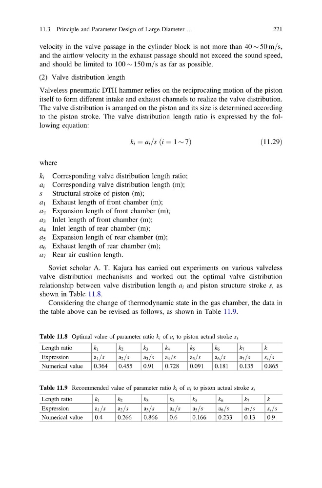
Soviet scholar A. T. Kajura has carried out experiments on various valveless
valve distribution mechanisms and worked out the optimal valve distribution
relationship between valve distribution length a i and piston structure stroke s, as
shown in Table 11.8.
Considering the change of thermodynamic state in the gas chamber, the data in
the table above can be revised as follows, as shown in Table 11.9.
Table 11.8 Optimal value of parameter ratio k i of a i to piston actual stroke s s
Length ratio
k 1
k 2
k 3
k 4
k 5
k 6
k 7
k
Expression
a 1 =s
a 2 =s
a 3 =s
a 4 =s
a 5 =s
a 6 =s
a 7 =s
s s =s
Numerical value
0.364
0.455
0.91
0.728
0.091
0.181
0.135
0.865
Table 11.9 Recommended value of parameter ratio k i of a i to piston actual stroke s s
Length ratio
k 1
k 2
k 3
k 4
k 5
k 6
k 7
k
Expression
a 1 =s
a 2 =s
a 3 =s
a 4 =s
a 5 =s
a 6 =s
a 7 =s
s s =s
Numerical value
0.4
0.266
0.866
0.6
0.166
0.233
0.13
0.9
11.3 Principle and Parameter Design of Large Diameter …
221
and the airflow velocity in the exhaust passage should not exceed the sound speed,
and should be limited to 100 $ 150 m=s as far as possible.
(2) Valve distribution length
Valveless pneumatic DTH hammer relies on the reciprocating motion of the piston
itself to form different intake and exhaust channels to realize the valve distribution.
The valve distribution is arranged on the piston and its size is determined according
to the piston stroke. The valve distribution length ratio is expressed by the following equation:
k i ¼ a i =s i ¼ 1 $ 7
ð
Þ
ð 11:29Þ
where
k i Corresponding valve distribution length ratio;
a i Corresponding valve distribution length (m);
s Structural stroke of piston (m);
a 1 Exhaust length of front chamber (m);
a 2 Expansion length of front chamber (m);
a 3 Inlet length of front chamber (m);
a 4 Inlet length of rear chamber (m);
a 5 Expansion length of rear chamber (m);
a 6 Exhaust length of rear chamber (m);
a 7 Rear air cushion length.
Soviet scholar A. T. Kajura has carried out experiments on various valveless
valve distribution mechanisms and worked out the optimal valve distribution
relationship between valve distribution length a i and piston structure stroke s, as
shown in Table 11.8.
Considering the change of thermodynamic state in the gas chamber, the data in
the table above can be revised as follows, as shown in Table 11.9.
Table 11.8 Optimal value of parameter ratio k i of a i to piston actual stroke s s
Length ratio
k 1
k 2
k 3
k 4
k 5
k 6
k 7
k
Expression
a 1 =s
a 2 =s
a 3 =s
a 4 =s
a 5 =s
a 6 =s
a 7 =s
s s =s
Numerical value
0.364
0.455
0.91
0.728
0.091
0.181
0.135
0.865
Table 11.9 Recommended value of parameter ratio k i of a i to piston actual stroke s s
Length ratio
k 1
k 2
k 3
k 4
k 5
k 6
k 7
k
Expression
a 1 =s
a 2 =s
a 3 =s
a 4 =s
a 5 =s
a 6 =s
a 7 =s
s s =s
Numerical value
0.4
0.266
0.866
0.6
0.166
0.233
0.13
0.9
11.3 Principle and Parameter Design of Large Diameter …
221